Operating Instructions
GM35
Probe Model
Specifications, consumables and spare parts
8009389/07-2006
©
SICK MAIHAK GmbH • Germany · All rights reserved
97
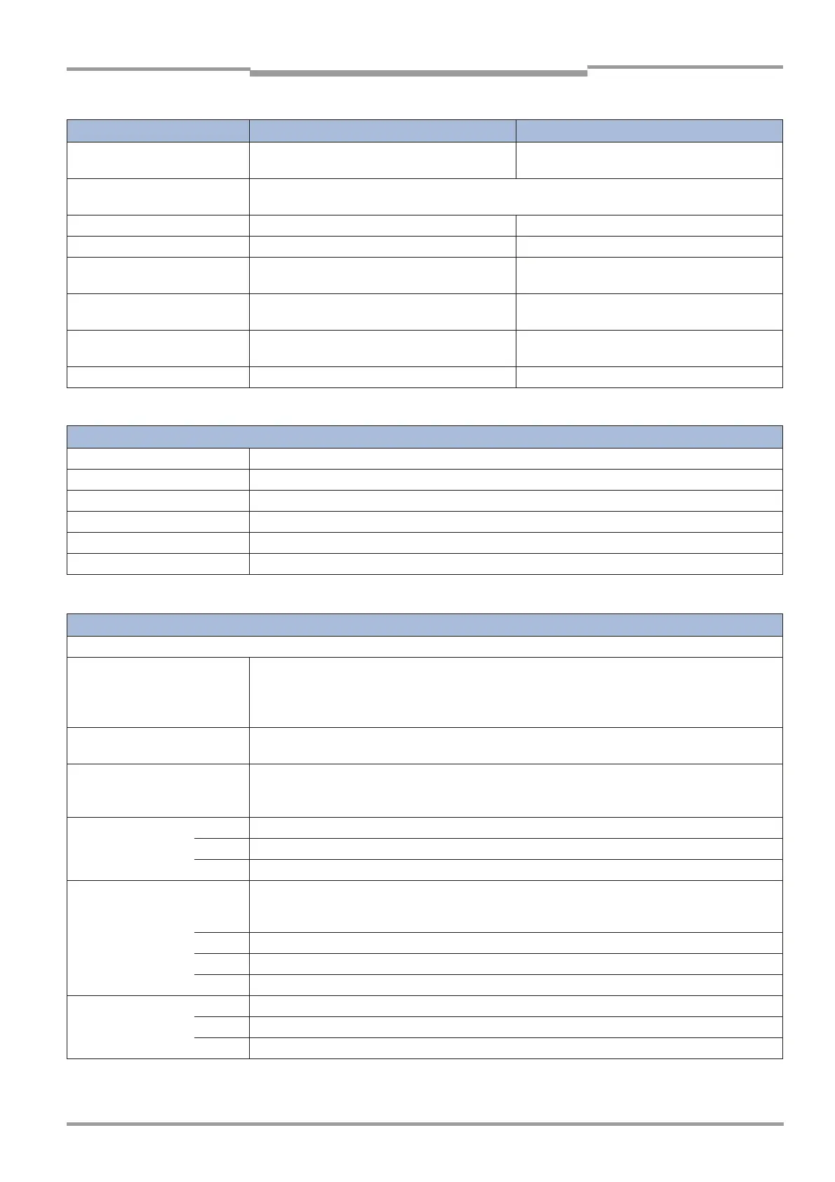
Measuring probe
Design Measuring distance open in flow direction;
purge air supply required
Gas diffusion probe; different versions available
for dry and wet measuring gas
Reflector The reflectors of all GM 35 variants for the CO measuring chanal are gold coated; the reflectors of
the other versions are full triple of quartz glass.
Integrated sensors For measuring gas temperature and pressure For measuring gas temperature and pressure
Data transfer CAN bus (electrically isolated) CAN bus (electrically isolated)
Heating for optical boundary
surfaces
– With integrated heater controller
Power supply Provided by the GM35 SR unit via the CAN bus
interface cable
Separate supply: 115/230 V AC; 50/60 Hz;
power consumption: max. 150 W
Dimensions and active
measuring paths
See Page
page 99
See Page
page 101
Weight max. 25 kg max. 45 kg
Measuring probe data
Purge-air unit
Power supply (three-phase)
Δ
200–240 V, Y 345–415 V at 50 Hz
Δ
220–275 V, Y 380–480 V at 60 Hz
Rated current
Δ
2.6 A / Y 1.5 A at 50 Hz
Δ
2.3 A / Y 1.3 A at 60 Hz
Motor rating 0.35 kW at 50 Hz 0.45 kW at 60 Hz
Delivery rate min. 40 m
3
/h
Dimensions (W x H x D) 550 x 550 x 270 mm
Weight 14 kg
Purge-air unit
data
GM35 Evaluation Unit
Connections/interfaces
Data transfer within the GM35
measuring system (to SR unit,
measuring probe, optional
O
2
analyzer)
CAN bus
•
Max. cable length 1000 m
•
Electrically isolated
•
Connects evaluation unit, SR unit and measuring probe
Data interface to customer mea-
surement value computer/host)
Optional:
•
PROFIBUS (EN 50170)
Service interface for PC RS 232
•
Connected via 9-pin Sub-D socket
•
Modem capability
Analog outputs x 3 Output range: 0–20 mA, max. 500
Ω
, electrically isolated, live zero can be set to 4 mA
A1–A3 Measurement values; can be assigned individually
Analog input 0 ... 20 mA, 100
Ω
Status outputs x 3 Relays, NO contacts
DC max. 30 W, 48 V, 1 A
AC max. 60 W, 48 V, 1 A
R1 Malfunction
R2 Maintenance request
R3 Functional check
Status inputs x 3 Inputs for external relay contacts (contact load 24 V, voltage supplied by GM35 Evaluation unit)
E1 Check cycle
E2 Autocal GM35
GM35 Evaluation Unit (Section 1 of 2)

 Loading...


