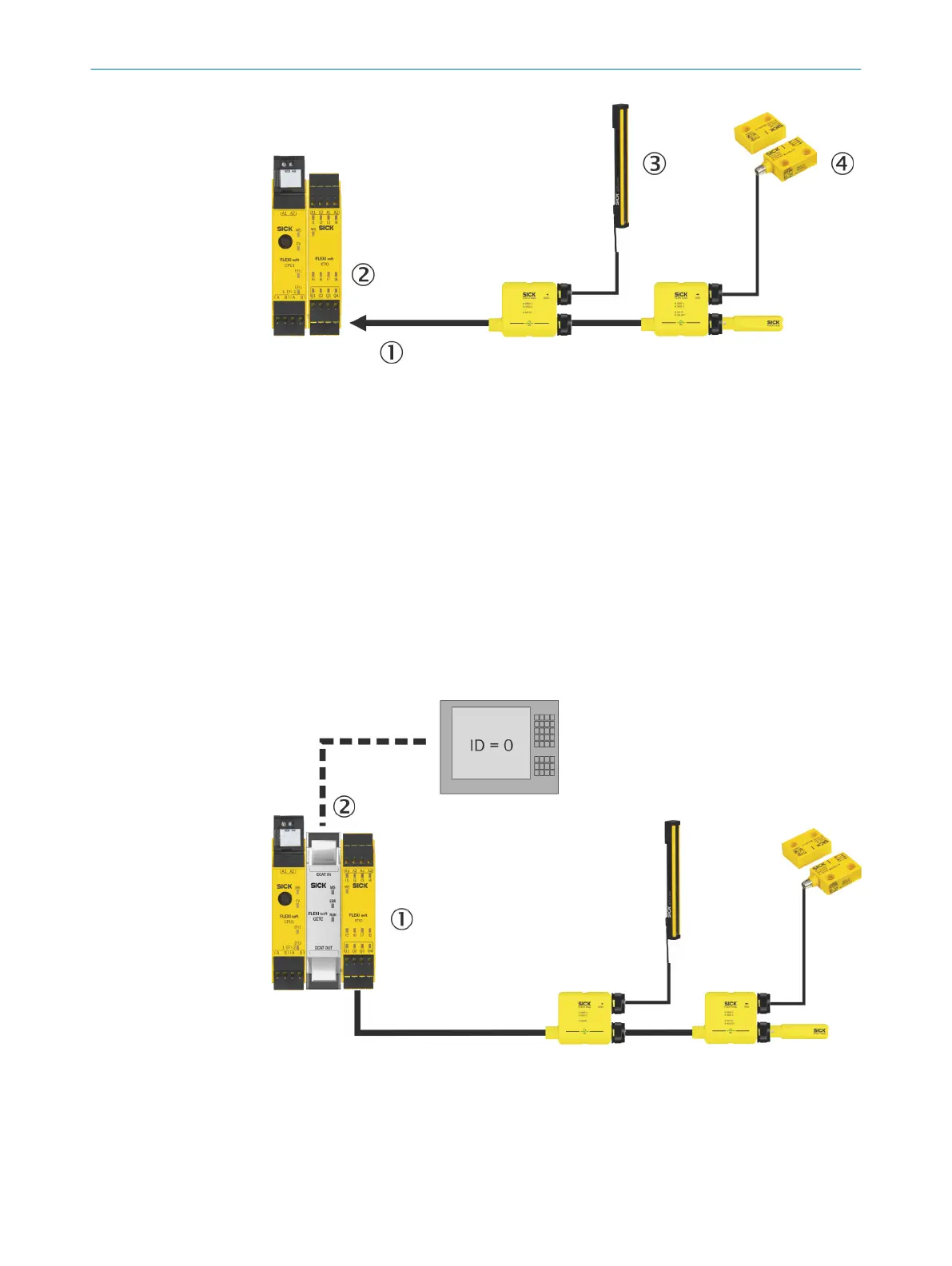
Figure 5: Safe cut-off path
1
Safe cut-off path
2
I/O module for the Flexi Soft safety controller
3
Safety sensors with monitored semiconductor output (OSSD)
4
Electro-mechanical safety switches
Diagnostic information
N
on-safe diagnostic information about the statuses inside the safe sensor cascade and
about the Flexi Loop nodes is also sent to the Flexi Soft safety controller.
Further processing of information in the logic editor
The safety information and the non-safe diagnostic information can undergo further
processing in the logic of the Flexi Soft safety controller (see the “Flexi Loop in the Flexi
Soft Designer” operating instructions, part no. 8014522) or it can be forwarded to a
PLC, for example, via a gateway.
Figure 6: Further processing of information
1
Gateway
2
Diagnostic information
3 PRODUCT DESCRIPTION
16
O P E R A T I N G I N S T R U C T I O N S | Flexi Loop 8015836/YT10/2016-05-24 | SICK
Subject to change without notice