Via PWRI power supply accessory (recommended)
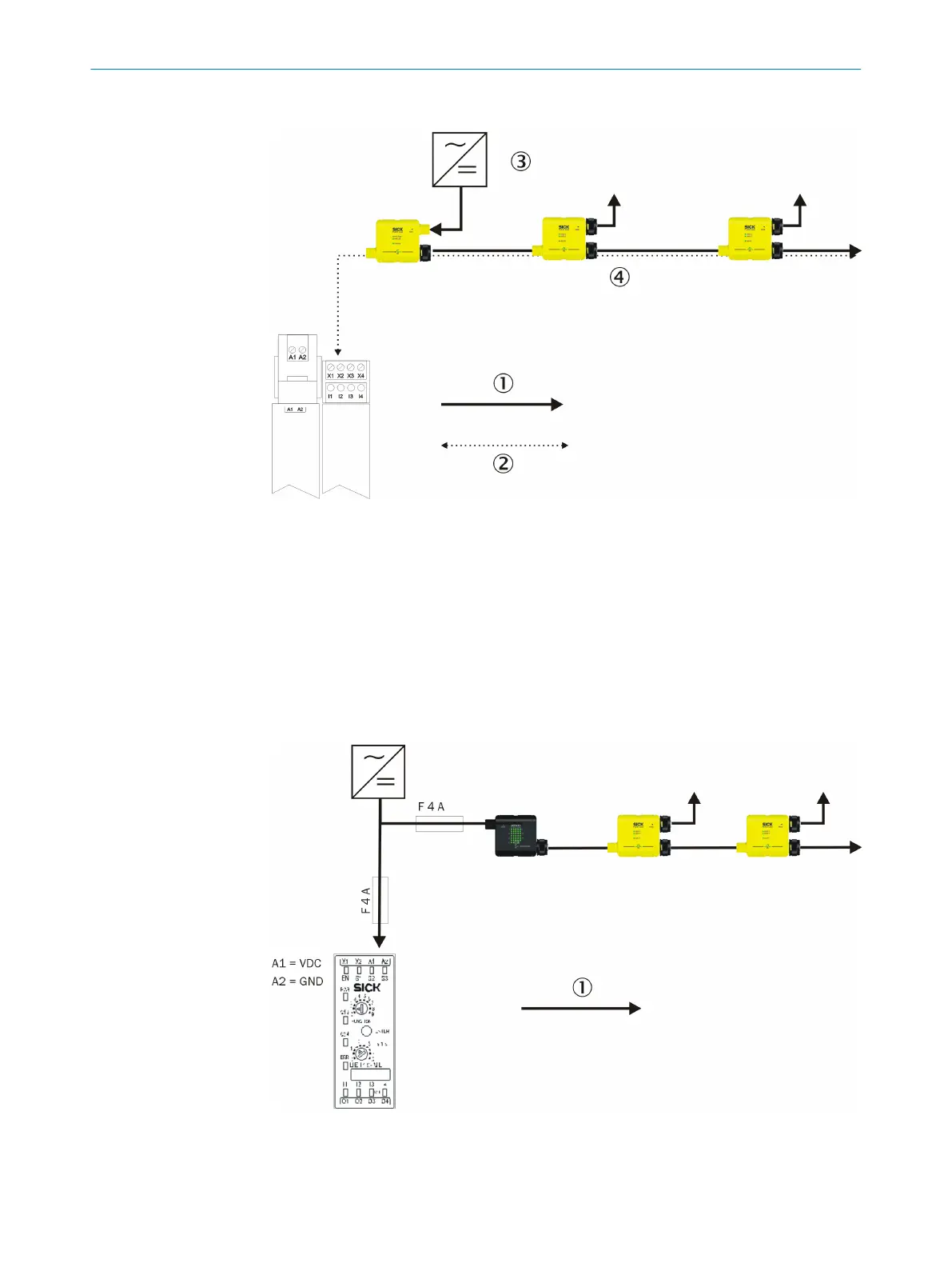
Figure 27: Connection via PWRI power supply accessory
1
Power flow
2
Data flow
3
Power supply
4
Max. 4 A
If you supply a safe sensor cascade via the PWRI power supply accessory, this acces‐
sor
y will monitor the current and shut down in case of overcurrent. In addition the oper‐
ating voltage in each section is monitored.
To the power source for the Flexi Classic safety controller
Figure 28: Direct connection to the power source for the Flexi Classic safety controller
1
Power flow
DESIGN 4
8015836/YT10/2016-05-24 | SICK O P E R A T I N G I N S T R U C T I O N S | Flexi Loop
29
Subject to change without notice