Figure 57: Commands and parameters in the IODD
1
Parameter
2
Parameter Menu
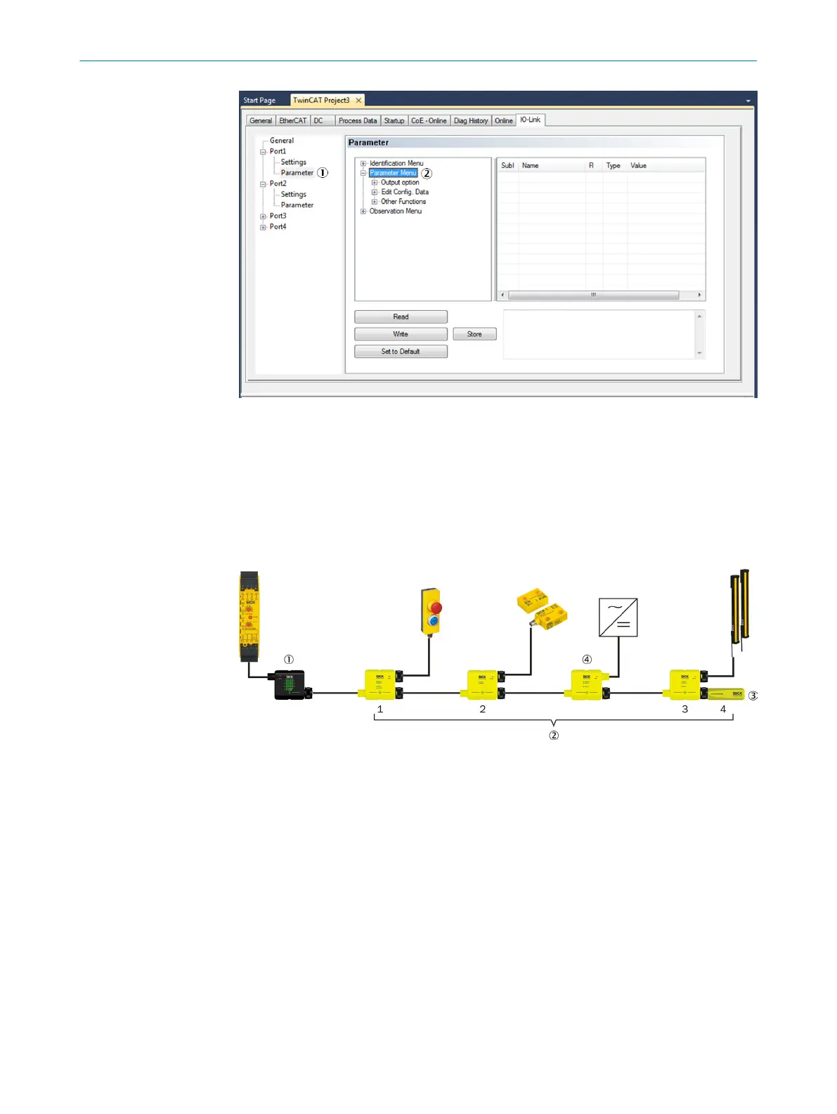
7.4.2.1 Configuration of the Flexi Loop nodes
A safe sensor cascade can contain up to 32 Flexi Loop nodes. The logical numbering 2
s
tarts after the MSTR2 Flexi Loop accessory 1 at the first Flexi Loop node connected
and ends with the terminator 3.
Figure 58: Logical numbering of the Flexi Loop nodes
1
MSTR Flexi Loop accessory
2
Logical numbering of the Flexi Loop nodes and the terminator
3
Terminator
4
Flexi Loop accessories (in the example PWRI)
Flexi Loop accessories (in the example PWRI) 4 can be connect
ed between the Flexi
Loop nodes. Flexi Loop accessories are not given a logical number.
Defining number and types
In the configuration from the factory the first position contains a Flexi Loop node
FLN-EMSS1100108 and the second position a terminator. You define the actual num‐
ber and the types of the Flexi Loop nodes.
b
Log into the configuration software for the standard controller as Specialist.
b
Change to Parameter on the IO-Link port used.
7 C
ONFIGURATION
58
O P E R A T I N G I N S T R U C T I O N S | Flexi Loop 8015836/YT10/2016-05-24 | SICK
Subject to change without notice