76
8009441/YN36/V3-0/2015-08| SICKOPERATING INSTRUCTIONS|GM35
Subject to change without notice
START-UP
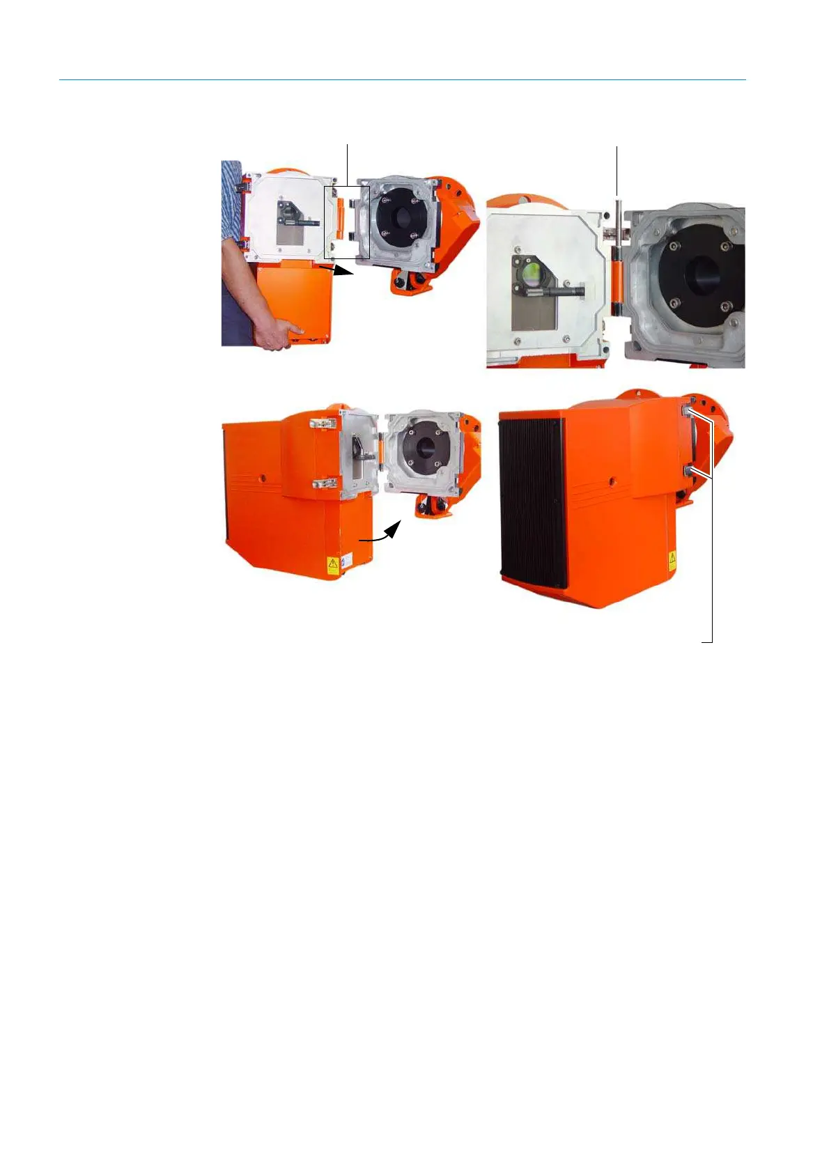
Fig. 57: Assembly steps for installing the sender/receiver unit
6. Installing the reflector head
▸ Attach the reflector head to the device flange:
– Assemble the hinge and insert the bolt
▸ Swivel the reflector head closed when necessary and secure the enclosure with the
quick-release fasteners.
Hinge Bolt
Quick-release fasteners

 Loading...


