Table 59: Function of the output
Output number Function
1 Provides the decoded value as an integer.
Table 60: Possible values
Input 4 (2
3
) Input 3 (2
2
) Input 2 (2
1
) Input 1 (2
0
) Output 1
x 0 1 0 x +2
0 0 1 0 2
1 0 1 0 10
Output 1 is link
ed to the Speed Enable ID input of the Position Monitor function block. This
means that the signal from the CPU (input 4) activates either speed ID 2 (minimum
speed/speed ID 1 = 0) or speed ID 10 (maximum speed).
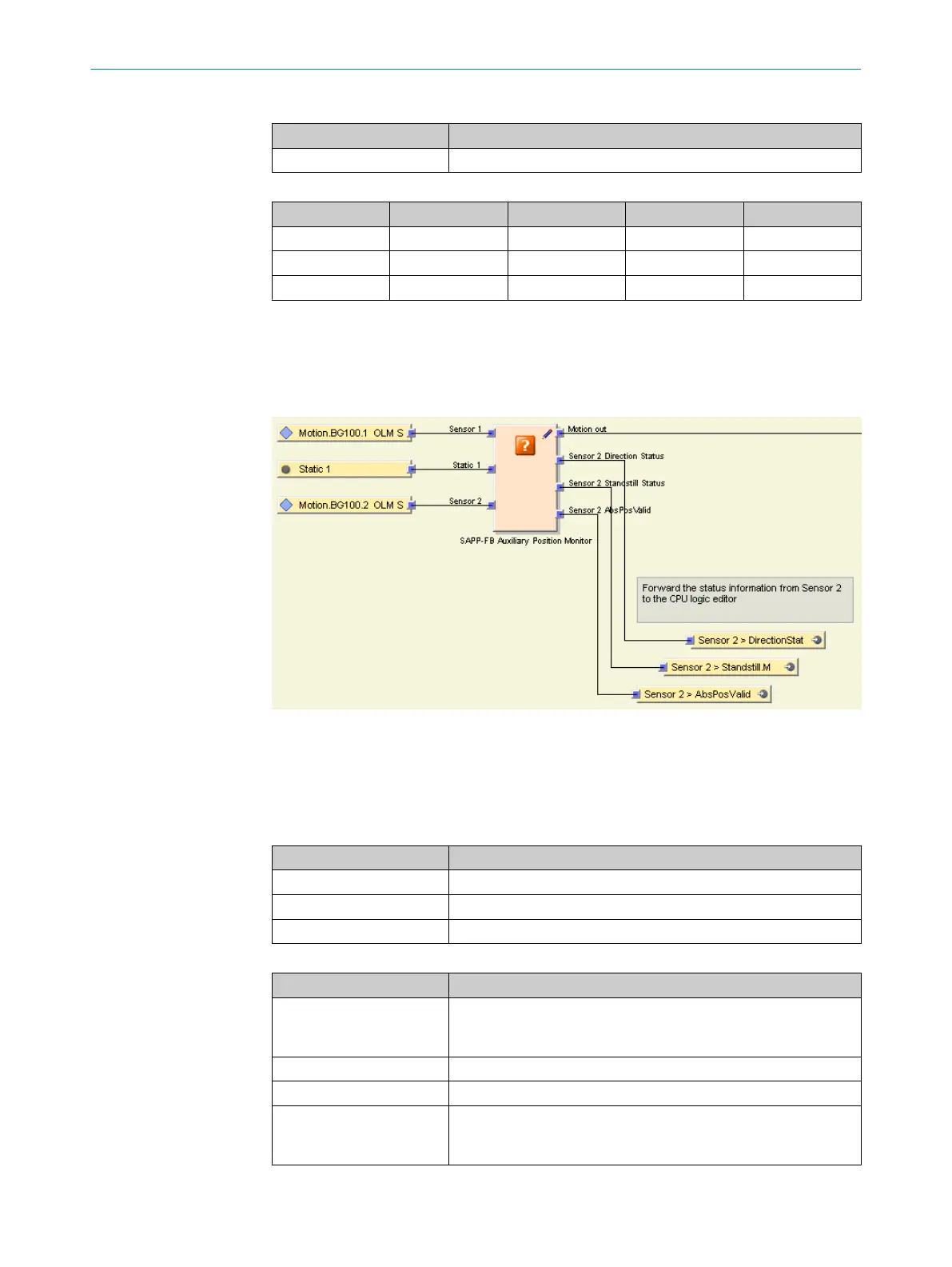
7.6.2.2 Auxiliary Position Monitor SAPP-FB function block (application-specific)
Figure 45: Function block view - Auxiliary Position Monitor SAPP-FB
T
he application-specific Auxiliary Position Monitor SAPP-FB function block generates status
information from sensor 2. The function block also prepares the Motion signal for the
Position Monitor function block, which must be configured by the user.
Table 61: Function of the inputs
Input name Function
Sensor 1 BG100.1 OLM sensor 1 (at MOC1 input ENC1)
Sensor 2 BG100.2 OLM sensor 2 (at MOC1 input ENC2)
Static 1 Signal High for the function block
Table 62: Function of the outputs
Output name Function
Motion out (Mo
tion data type) The Motion data type adds additional diagnostics information to all
information provided by sensor 1. In this case, the diagnostics
information only relates to sensor 1.
Sensor 2 Direction Status The status bit of sensor 2 is forwarded to the CPU logic.
Sensor 2 Standstill Status The status bit of sensor 2 is forwarded to the CPU logic.
Sensor 2 AbsPosValid The position data from sensor 2 is checked to ensure that it is
v
alid (1 = valid/0 = invalid). The status bit is forwarded to the CPU
logic.
CONFIGURATION 7
8020941/12O9/2019-08-05 | SICK O P E R A T I N G I N S T R U C T I O N S | Safe Linear Positioning
67
Subject to change without notice