Chapter 7 Operating instructions
S100
36 © SICK AG • Subject to change without notice 8012238/YY30/2015-02-20
pplication examples and
7 Application examples and connection diagrams
The examples shown are only provided as an aid for your planning. You may need to
consider additional protection measures for your application.
Ensure that there is adequate arc-suppression at the relays/contactors. Take into
account that arc-suppressors may lengthen the response time.
The arc-suppressors must be in parallel with the relays/contactors (not across the
contacts).
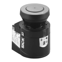
7.1 Applications with the S100 Standard
Warehouse bay monitoring by S100 on a shelving access device.
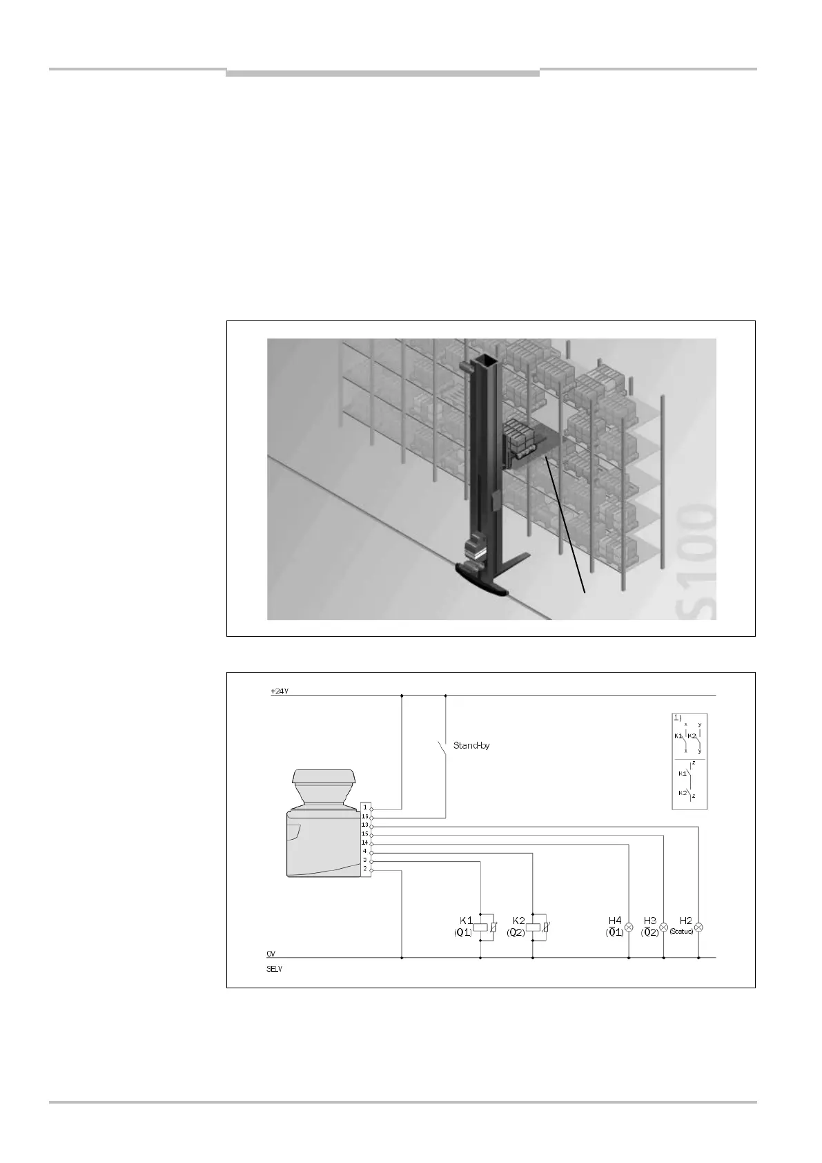
S100 Standard in connection with relays/contactors on the switching outputs Q1 and Q2.
The LEDs H4 and H3 connected to the outputs 1 and 2 indicate the status of the
related switching output. The LED H2 connected to the application diagnostic output
indicates the state (error/contamination) of the S100.
Notes
Fig. 24: Application with a
S100 Standard
Fig. 25: Connection diagram
S100 Standard