Chapter 5 Operating instructions
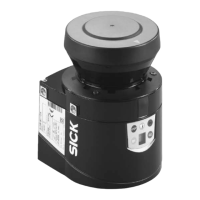
S100
26 © SICK AG • Subject to change without notice 8012238/YY30/2015-02-20
5.1 Definition of the size of the switching field for mobile
applications
To be able to prevent collisions between vehicles or vehicles and fixed objects, the length
and width of the switching field must be adequately dimensioned.
When calculating the length of the switching field, take into account the vehicle’s stopping
distance. This comprises
braking distance, to be found in the vehicle documentation
distance covered during the response time of the vehicle controller, to be found in the
vehicle documentation
the distance covered during the laser scanner’s response time
The distance covered during the laser scanner’s response time depends on the laser
scanner’s response time and the maximum speed of the vehicle in your mobile
application.
You will find the response time T
S
for the laser scanner in section 12.2 “Response
times” on page 53.
We recommend a supplement of 100 mm to the switching field length to stop the
vehicle before a possible collision.
If there are retroreflectors in the vehicles’ path or if it is to be expected that the vehicle
braking force will fade, you may need to increase the recommended supplement in
certain circumstances.
The width of the switching field should cover the width of the vehicle. In addition, you
should configure a supplement of 100 mm on each side.
5.2 Mounting steps
Special features to note during mounting:
Mount the S100 such that it is protected from moisture, dirt and damage.
Ensure that the entire field of view of the S100 is not restricted.
Mount the laser scanner such that the indicators are easy to see.
Always mount the S100 so that there is still enough space for mounting and removing
the system plug.
Avoid excessive shock and vibration loading on the laser scanner.
On applications that suffer from heavy vibration, prevent the fixing screws from coming
loose using screw locking devices.
Regularly check the tightness of the fixing screws.
The origin of the scan plane is 116 mm above the bottom edge of the S100 (see
section 12.4.3 “Scan plane origin” on page 62).
There are three possible ways of fixing the S100:
direct mounting without mounting kit
mounting with mounting kit 1a or 1b
mounting with mounting kit 2 (only in conjunction with mounting kit 1a or 1b)
You will find the part numbers for the mounting kits in section 13.3.1 “Mounting kits” on
page 63.
Pay attention to the maximum torque of the M5 fixing screws on the S100 of max. 5.9 Nm.
Notes
Note

 Loading...