Chapter 11 Operating instructions
S100
46 © SICK AG • Subject to change without notice 8012238/YY30/2015-02-20
11 Diagnostics
This chapter describes how to identify and remedy errors and malfunctions during the
operation of the laser scanner.
11.1 SICK support
If you cannot remedy an error with the help of the information provided in this chapter,
please contact your local SICK representative.
Make a note of the telephone number of your SICK subsidiary so that you or other users
have this number easily at hand. You will find the telephone number on the rear of these
operating instructions.
Telephone number of your SICK subsidiary
11.2 Error and status indications on the LEDs
This section describes the meaning of the indications and LED error messages and how
you can respond. You will find a description of the indicators in section 4.6 “Status
indicators” on page 24, the connections for the outputs in section 6.1 “System
connection” on page 32.
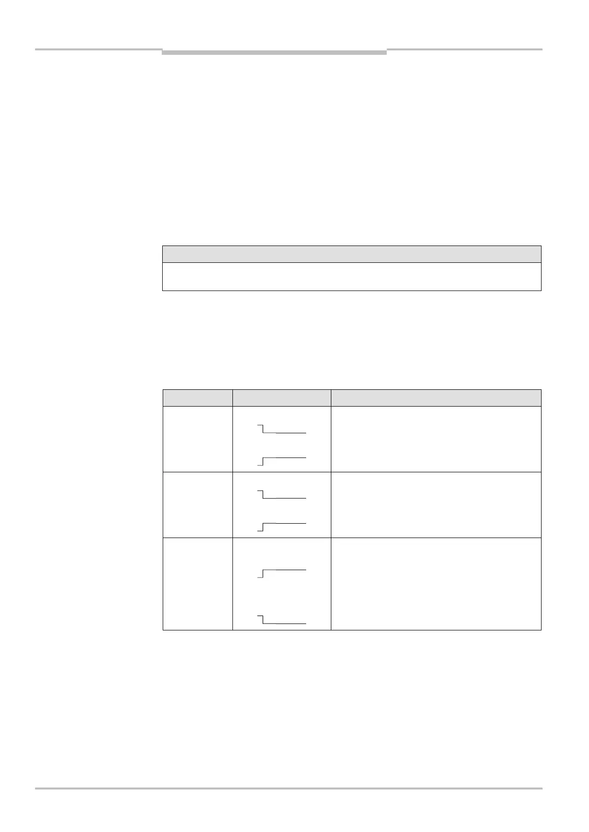
Display Output level Possible cause
On switching output Q1
On switching output 1
Object in switching field 1
switching output Q1 in the OFF state
switching output 1 in the ON state
On switching output Q2
On switching output 2
Object in switching field 1
switching output Q2 in the OFF state
switching output 2 in the ON state
On switching outputs
Q1 and Q2
On switching outputs
1 and 2
Switching fields free
switching outputs Q1 and Q2 in the ON state
switching outputs 1 and 2 in the OFF state
Tab. 19: Status indicators
during operation
 Loading...