Operating instructions Chapter 7
S100
8012238/YY30/2015-02-20 © SICK AG • Subject to change without notice 37
Application examples and
connection diagrams
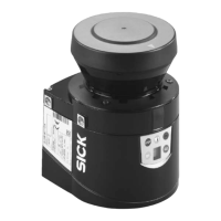
7.2 Applications with the S100 Professional
Distance monitoring by S100 Professional on an electrical overhead conveyor.
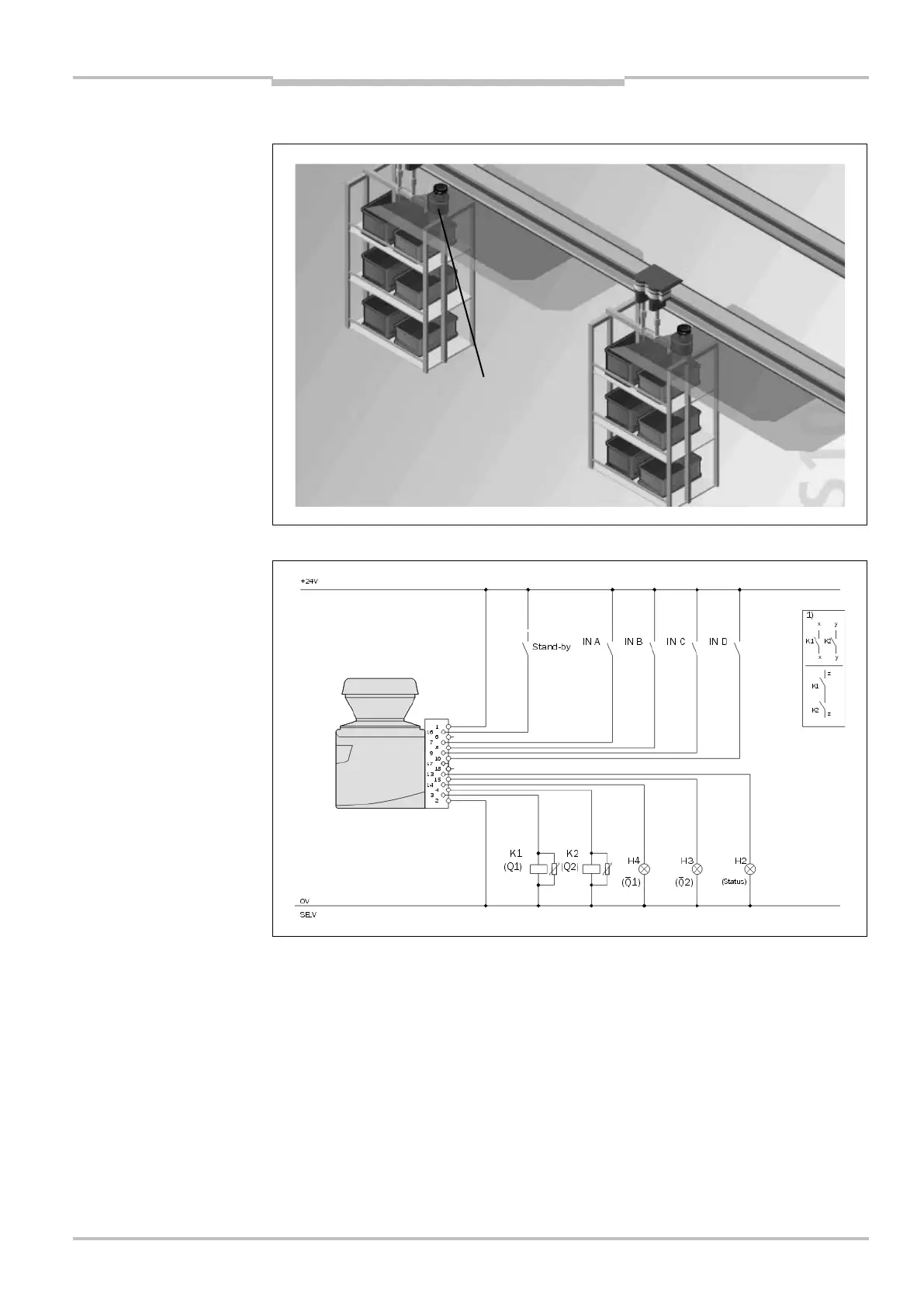
S100 Professional in connection with relays/contactors, switching field switching using
static inputs A, B, C and D. The LEDs H4 and H3 connected to the outputs 1 and 1
indicate the status of the related switching output. The LED H2 connected to the
application diagnostic output indicates the state (error/contamination) of the S100.
Fig. 26: Application with a
S100 Professional
Fig. 27: Connection diagram
S100 Professional
 Loading...