Operating instructions Chapter 5
S100
8012238/YY30/2015-02-20 © SICK AG • Subject to change without notice 29
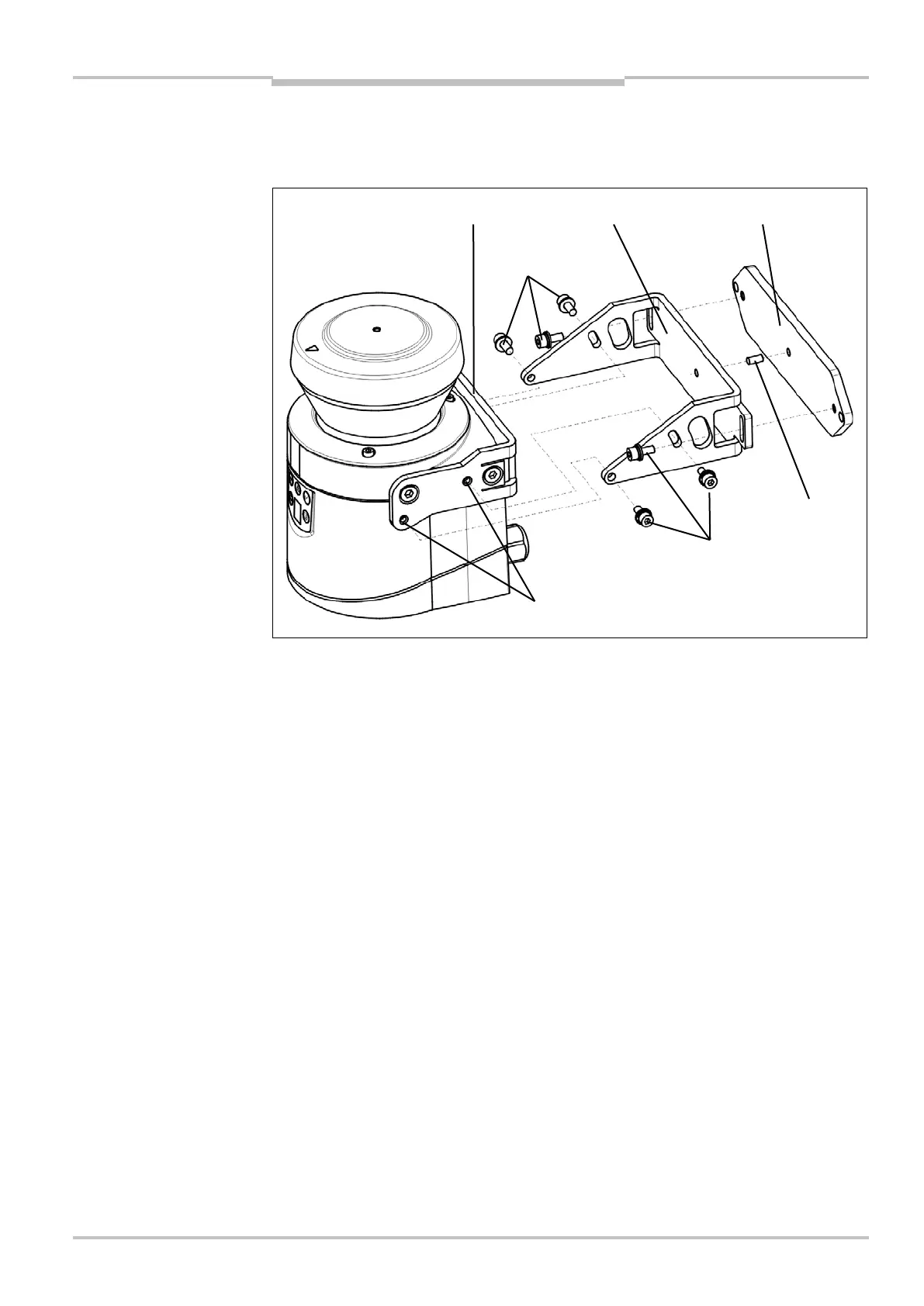
5.2.3 Mounting with mounting kit 2 and 3
With the aid of mounting kits 2 and 3 (only in conjunction with mounting kit 1a or 1b) you
can align the S100 in two planes. The maximum adjustment angle is ±11° in both planes.
Mount mounting kit 1a or 1b to the S100.
Mount the mounting kit 3 on the mounting surface.
Fit the centring pin (4 mm) in the central hole on mounting bracket 3.
Fit mounting kit 2 to mounting kit 3 and mount it using two fixing screws M4×10.
Then mount the S100 on mounting kit 2 with the aid of the threaded holes in mounting
kit 1a.
Adjust the S100 longitudinally and transversely and then tighten the six fixing screws on
the mounting kits.
During mounting, please observe the dimensional drawings (see section 12.4 “Dimen-
sional drawings” on page 60).
5.2.4 Using multiple S100 laser scanners
The S100 is so designed that mutual interference between several laser scanners is
unlikely. To completely exclude erroneous switching, we recommend mounting the laser
scanners as shown in the following examples.
Use mounting kits 1 to 3 to adjust the laser scanners to different angles (see
section 13.3.1 “Mounting kits” on page 63).
Fig. 15: Mounting with
mounting kit 2
Note
 Loading...


