Chapter 14 Operating instructions
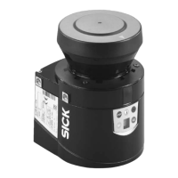
S100
68 © SICK AG • Subject to change without notice 8012238/YY30/2015-02-20
14.3 List of tables
Tab. 1: Overview on disposal by components .................................................................... 11
Tab. 2: Functions of the S100 variants .............................................................................. 13
Tab. 3: Scanning ranges for the fixed resolutions that can be set ................................... 20
Tab. 4: Example for monitoring case switching with the S100 Professional ................... 22
Tab. 5: Figure from experience for the necessary input delay .......................................... 22
Tab. 6: Terminal assignment on the system plug .............................................................. 33
Tab. 7: Use the cable glands supplied ............................................................................... 34
Tab. 8: Recommended wire cross-sections ....................................................................... 35
Tab. 9: Pin assignment pre-assembled system plug ......................................................... 35
Tab. 10: Status of the outputs (CAN IO State — Outputs) .................................................... 39
Tab. 11: Status of the inputs (CAN IO State — Inputs) ......................................................... 40
Tab. 12: Active switching fields (CAN Field Data) ................................................................ 40
Tab. 13: Device status (CAN Device State) .......................................................................... 40
Tab. 14: Status of the virtual inputs (CAN Virtual Input State)............................................ 41
Tab. 15: 7segment display during and after the power up sequence on initial
commissioning ........................................................................................................ 42
Tab. 16: LED indication after the power up sequence ........................................................ 42
Tab. 17: 7segment display during and after the power up sequence on re-
commissioning ........................................................................................................ 43
Tab. 18: LED indication after the power up sequence ........................................................ 43
Tab. 19: Status indicators during operation......................................................................... 46
Tab. 20: LED error messages ................................................................................................ 47
Tab. 21: Error and status indications on the 7segment display ........................................
48
Ta
b. 22: Examples for levels of remission of various materials.......................................... 52
Tab. 23: Supplements for multiple sampling ....................................................................... 53
Tab. 24: Data sheet S100 ..................................................................................................... 54
Tab. 25: Part numbers systems ............................................................................................ 63
Tab. 26: Part numbers mounting kit ..................................................................................... 63
Tab. 27: Part numbers system plugs S100 .......................................................................... 64
Tab. 28: Part numbers service cables .................................................................................. 64
Tab. 29: Part numbers self assembly connecting cables .................................................... 64
Tab. 30: Part numbers documentation ................................................................................ 64
Tab. 31: Part numbers miscellaneous .................................................................................. 65
 Loading...