Operating instructions Chapter 8
S100
8012238/YY30/2015-02-20 © SICK AG • Subject to change without notice 39
Ensure you do not lay the service cable close to powerful electrical drives or cables
carrying high currents. In this way you will avoid EMC effects on the service cable.
The service cable is only allowed to be connected for configuration and diagnostics. The
service cable must be disconnected and the protective cap fitted in operation.
To configure the device, please read the user manual for the CDS-S100 (Configuration &
Diagnostic Software — S100) and use the online help function of the program.
8.3 Configuration of the CANopen master
Use the Electronic Data Sheet for the S100 to configure the master. The functionality and
properties of the S100 are described in this data sheet in a standardised manner in ASCII
format. The Electronic Data Sheet for the S100 is on the CDS-S100 CDROM supplied.
(Configuration & Diagnostic Software — S100).
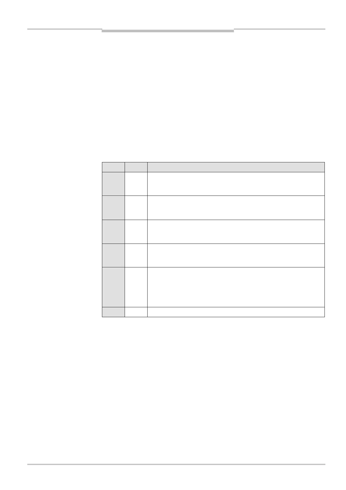
Data transfer over CANopen
Byte Bit Description
0 0 State of switching output Q1
0: Q1 inactive (switching field interrupted)
1: Q1 active (switching field free)
0 1 State of output 1
0: 1 inactive (switching field free)
1 active (switching field interrupted)
0 2 State of switching output Q2
0: Q2 inactive (switching field interrupted)
1: Q2 active (switching field free)
0 3 State of output 2
0: 2 inactive (switching field free)
2 active (switching field interrupted)
0 4-5 State of application diagnostic output “error/contamination”
0: Optics cover contaminated, no operation
1: Optics cover contaminated, still in operation
2: Device in the system status lockout
3: No error/no contamination
0 6-7 Reserved
Notes
outputs (CAN IO State —