Chapter 8 Operating instructions
S100
40 © SICK AG • Subject to change without notice 8012238/YY30/2015-02-20
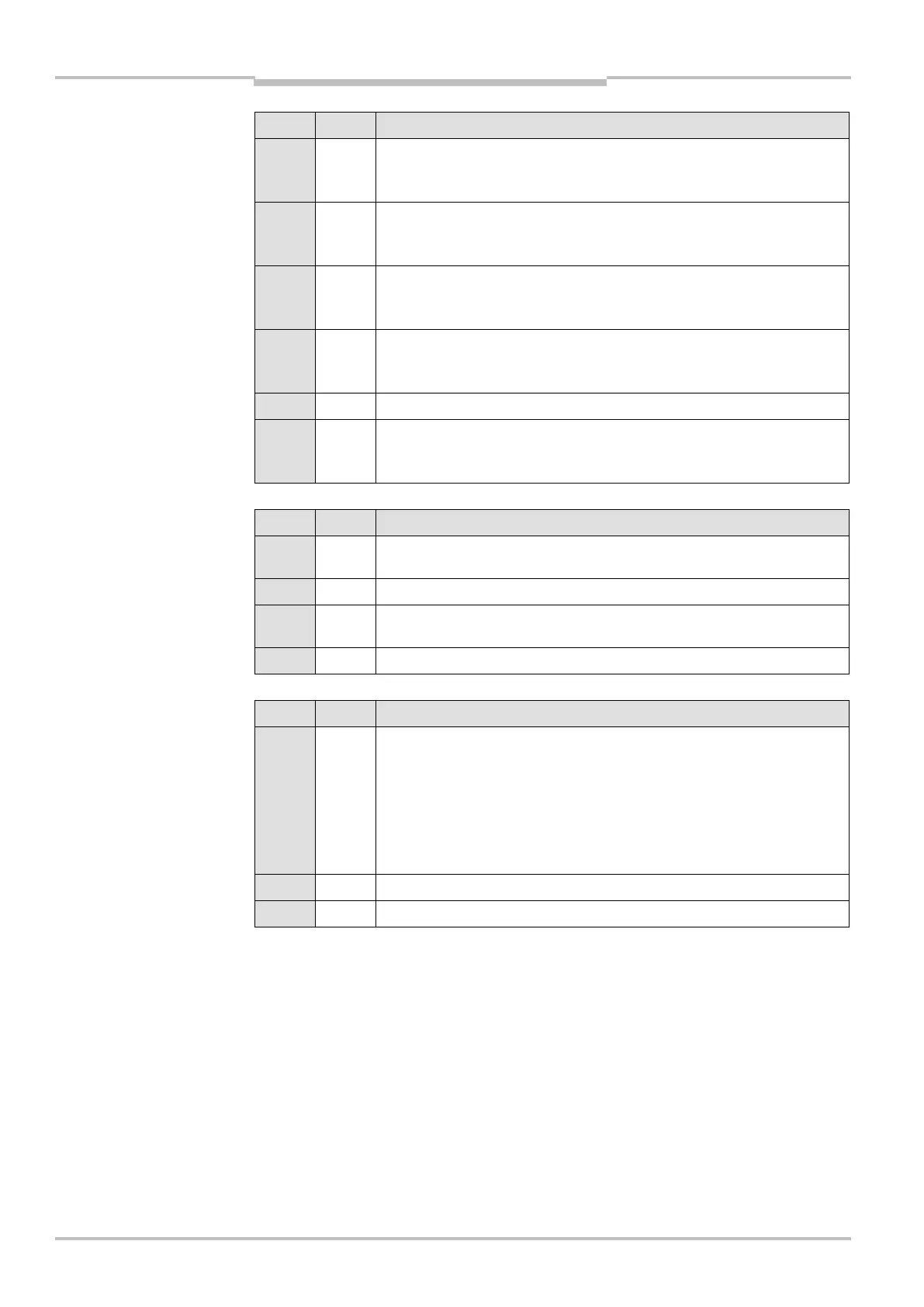
Byte Bit Description
1 0 State of control input A (S100 Professional only)
0: LOW
1 1 State of control input B (S100 Professional only)
0: LOW
1 2 State of control input C (S100 Professional only)
0: LOW
1 3 State of control input D (S100 Professional only)
0: LOW
1 4-6 Reserved
1 7 State of control input Stand-by mode
0: LOW
Byte Bit Description
2 0-4 Active switching field for switching output Q1
0 to 15: switching field 1 to 16
2 5-7 Reserved
3 0-4 Active switching field for switching output Q2
0 to 15: switching field 1 to 16
3 5-7 Reserved
Byte Bit Description
4 0-3 Device status
0: Device ready for operation
1: Waiting for configuration
2: System status lockout
3: Initialisation of the device
4: Waiting for valid input signals
5: Calibrating the optics cover
4 4-7 Reserved
5-7 0-7 Reserved
Tab. 11: Status of the inputs
(CAN IO State — Inputs)
Tab. 12: Active switching
fields (CAN Field Data)
Tab. 13: Device status
(CAN Device State)
 Loading...