Chapter 6 Operating instructions
S100
32 © SICK AG • Subject to change without notice 8012238/YY30/2015-02-20
6 Electrical installation
Switch the entire machine/system off line!
The machine/system could inadvertently start up while you are connecting the devices.
To prevent an unintentional start, ensure that the entire machine/system is
disconnected during the electrical installation.
Route all cables and connection cables such that they are protected from damage.
If you use screened cable, lay the screen evenly around the cable gland.
Ensure that the S100 is adequately protected electrically. You will find the electrical
data necessary for determining the correct fuse in section 12.3 “Data sheet” on
page 54.
Observe the requirements according to chapter 1 „Important safety notes“.
The electrical connections for the S100 are made at the system plug. A pre-assembled
connector variant and an un-assembled connector variant are available (see page 35).
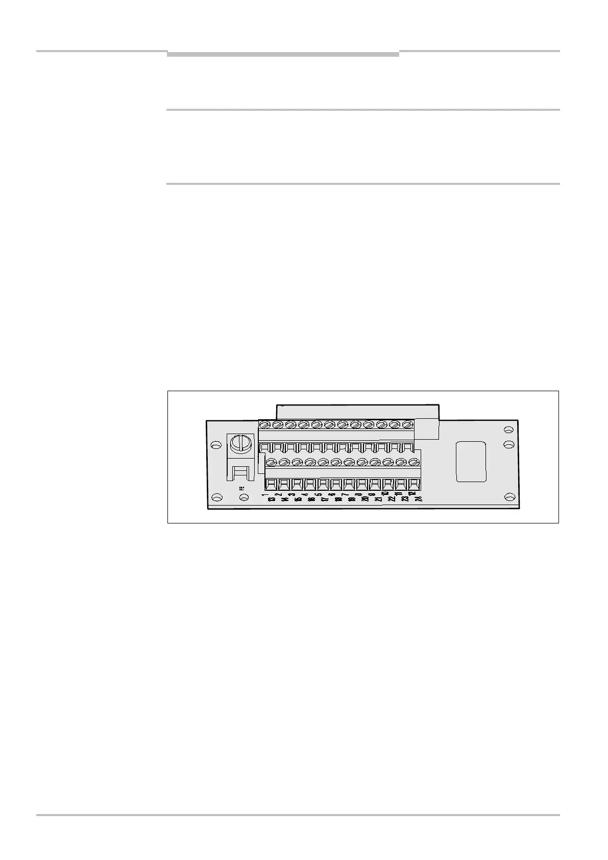
6.1 System connection
You will find all inputs and outputs of the S100 on the 24-pin screw terminal connection +
FE in the system plug.
The system connection pin assignments vary depending on the S100 variant.
If the cable gland/blanking plug is missing or not tightened, or if fixing screws are
missing or not tightened on the system plug, the IP 65 enclosure rating is not met.
All inputs and outputs on the S100 are to be used only in the context specified.
Notes
connection in the system
Notes

 Loading...


