Operating instructions Chapter 4
S100
8012238/YY30/2015-02-20 © SICK AG • Subject to change without notice 13
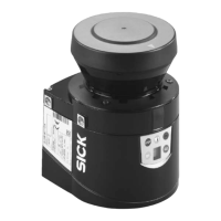
S100 variants
To cover different applications, two S100 variants are available.
Functions Standard Professional
Maximum switching field range [m] 10 10
Object resolution [mm] Maximum/
30/40/
50/70/150
Maximum/
30/40/
50/70/150
Switching fields
at 0.5° angular resolution 2 8
at 1.0° angular resolution 2 16
Programmable monitoring cases 1 16
Switching output 1 “allocated switching field free”
Switching output 2 “allocated switching field free”
Maximum source switching current on the switching
outputs 1 and 2 [mA]
250 250
Application diagnostic output 1 “allocated switching
field interrupted”
Application diagnostic output 2 “allocated switching
field interrupted”
Application diagnostic output “error/contamination”
Control inputs for switching between the monitoring
cases.
– 4
Stand-by mode
CANopen
Configuration memory in the system plug
4.3 Function
The S100 laser scanner can only operate correctly if the following conditions are met:
The control of the machine, system or vehicle must be electrical.
The S100 must be mounted and configured such that it detects objects as they enter
the monitored area (see chapter 5 “Mounting” on page 25 and chapter 9
“Commissioning” on page 42).
Tab. 2: Functions of the
S100 variants

 Loading...