Chapter 4 Operating instructions
S100
12 © SICK AG • Subject to change without notice 8012238/YY30/2015-02-20
4 Product description
This chapter provides information on the special features and properties of the S100 laser
scanner. It describes the construction and the operating principle of the device.
Please read this chapter before mounting, installing and commissioning the device.
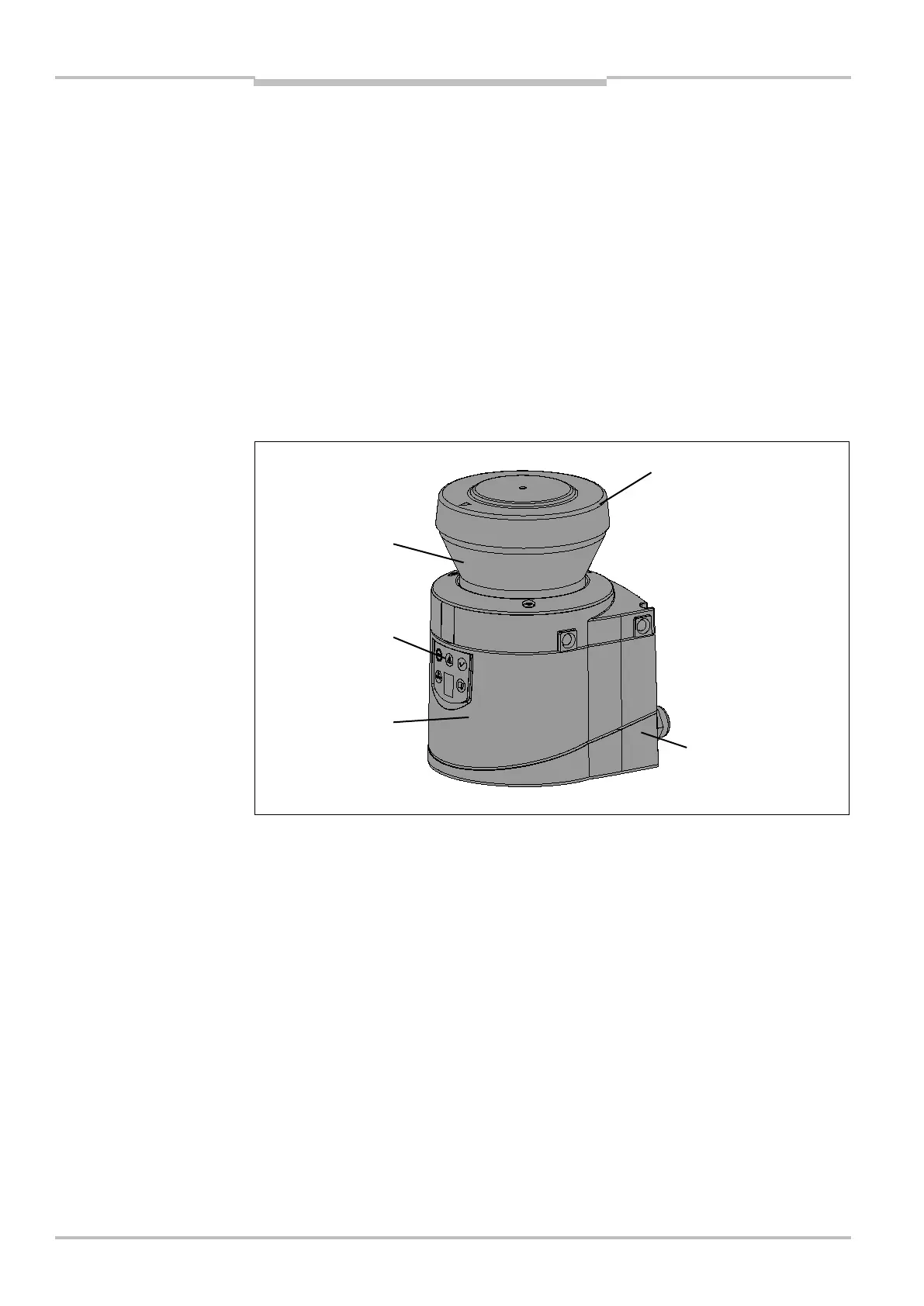
4.1 Device components
The S100 laser scanner comprises three components:
the sensor with the opto-electronic acquisition system, the LEDs and the 7segment
display
the optics cover with the window for the light output
the system plug with the configuration memory (the system plug contains all electrical
connections)
4.2 Special features
270° scanning angle
0.5° angular resolution
switching fields up to 10 m can be configured
CANopen integrated
status display with LEDs and 7segment display
minimum response time 40 ms
configuration using PC or notebook with SICK Configuration & Diagnostic Software —
S100
Configuration memory in the system plug. In case of device replacement, the existing
configuration is automatically transferred to the S100 newly connected. In this way
downtimes can be significantly reduced.
Optimal immunity to external light and dust due to dazzle and particle algorithms that
can be configured as required.
Fig. 1: Device components
7segment