Chapter 11 Operating instructions
S100
48 © SICK AG • Subject to change without notice 8012238/YY30/2015-02-20
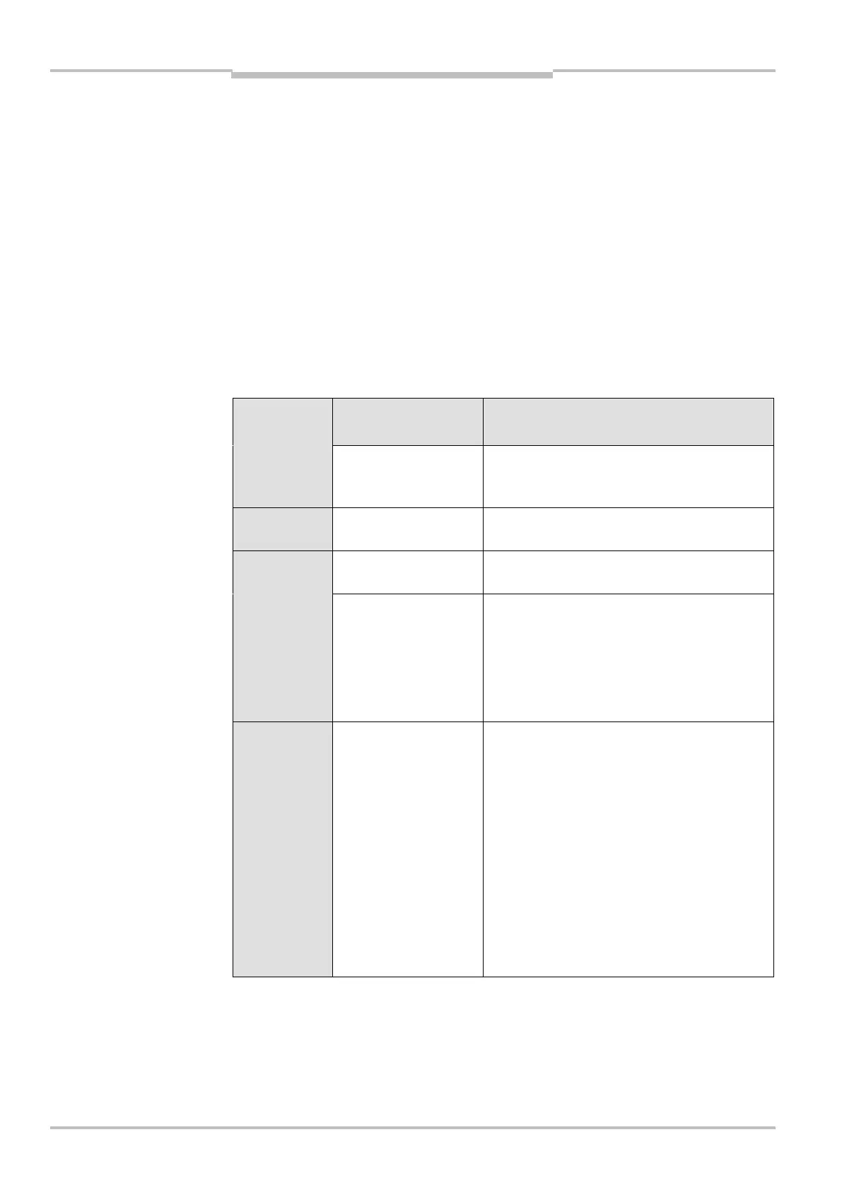
11.3 Error and status indications on the 7segment display
The system status lockout
In case of certain faults or an erroneous configuration, the system may change to the
lockout system status. The 7segment display on the laser scanner then indicates , ,
, , , , , , , , , or . To place the device back in operation, proceed as
follows:
Rectify the cause of the fault as per Tab. 21.
Switch the power supply for the S100 off and back on again.
Or
Restart the laser scanner with the aid of the CDS-S100.
This section explains the meaning of the error displays on the 7segment display and how
to respond to the messages. You will find a description of the positions and symbols on the
S100 in section 4.6 “Status indicators” on page 24.
Display/
(EMCY)
Possible cause Rectification of the error
, , , ,
, , ,
Power-up cycle — all
segments are
activated sequentially.
No error
Object in switching
field Q1
No error
Object in switching
field Q2
No error
Initialising the device The display goes out automatically when the
S100 is initialised.
If the display does not go off:
Check the system configuration with the aid
of the CDS-S100. Transfer the corrected
configuration to the S100 again.
(1010h)
Waiting for valid local
input signals
The display goes off automatically when an
input signal is present that corresponds to a
configured monitoring case.
If the display does not go off:
Check the cabling.
Check the control signals for correct
switching behaviour.
Check the system configuration with the aid
of the CDS-S100. Transfer the corrected
configuration to the S100 again.
Check the CANopen communication to the
bus master.
Tab. 21: Error and status
indications on the 7segment
display
EMCY = emergency
 Loading...