Chapter 4 Operating instructions
S100
24 © SICK AG • Subject to change without notice 8012238/YY30/2015-02-20
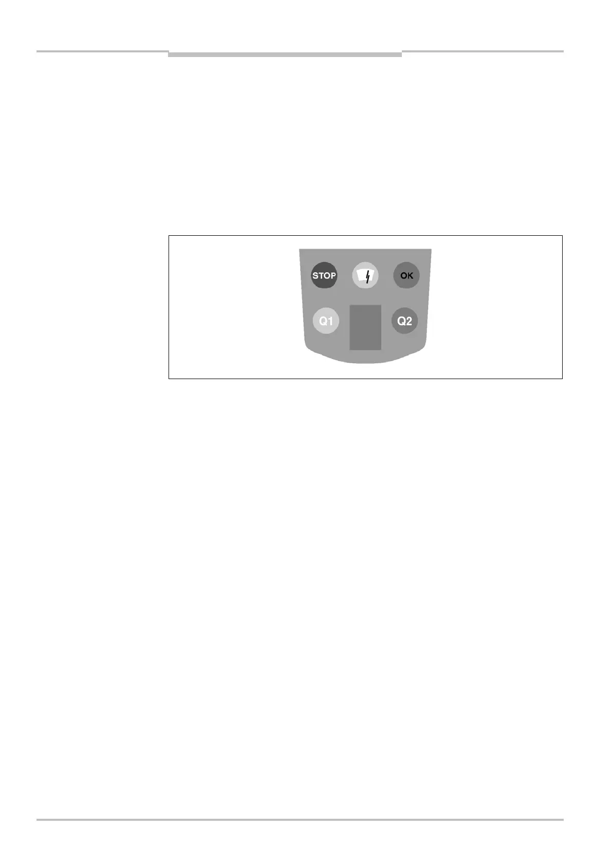
4.6 Status indicators
The S100 signals the operational status with the aid of the LEDs and the 7segment
display. These are on the front face of the laser scanner.
The depiction of numbers on the 7segment display can be rotated by 180° with the aid of
the CDS-S100 (Configuration & Diagnostic Software — S100). If the numbers are displayed
rotated, the point on the 7segment display goes out:
Point visible: The bottom edge of the numbers on the 7segment display is pointing
towards the bottom of the laser scanner.
Point not visible: The bottom edge of the numbers on the 7segment display is pointing
towards the optics cover.
The symbols have the following meaning:
Both switching outputs in the ON state (no object in the switching field)
One of the switching outputs in the OFF state (e.g. with an object in the switching field)
Optics cover contaminated
Switching output 1 in the OFF state
Switching output 2 in the OFF state
Fig. 11: Status indicators on
the S100