6 COMMISSIONING
8017768/12AX/2019-05-31|SICK
OPERATING INSTRUCTIONS | TIC
Subject to change without notice
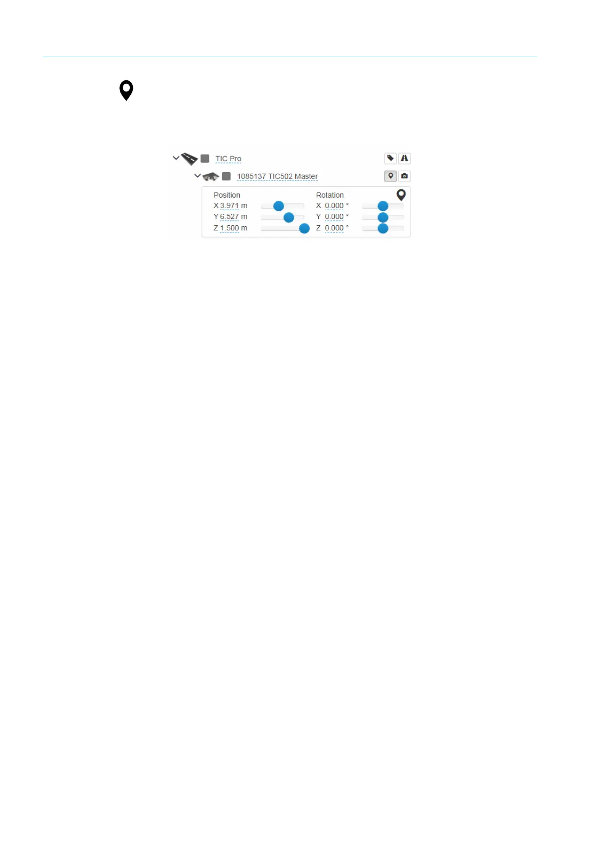
1. Go to the system function level in the navigation tree and click the Edit system
component position icon.
The input lines appear. These already contain the position values defined during rough
alignment.
2. The position and angle can be defined using either the slide controls or by entering the
values manually.
Place the mouse pointer on a slide control and turn the mouse wheel. The values
increase/decrease in “standard” increments. To increase/decrease the zoom
increments, simultaneously press and hold the Shift key or the Ctrl key, respectively.
3. Where necessary, adapt the view so that the effects of your changes are clearly visible
in the GUI.
When entering the position, please observe the alignment of the coordinate system:
• The X-axis lies straight across the width of the road. The first distance parameter X is
measured from the origin of the right-hand edge of the lane (when viewed in the
direction of travel).
• The Y-axis defines the height at which the component is mounted. The second distance
parameter Y is measured from the surface of the road.
• The Z-axis points in the direction of travel. The third distance value is measured in
relation to the measuring plane.
In most cases, you do not need to adjust the Z-value if you have selected the
components in the wizard. The value only needs to be adjusted if the components have
accidentally been displaced or were not added using the wizard.
The components can be rotated about the X-, Y-, and Z-axes.
• The components that are mounted overhead on the gantry must be attached so that
they point down vertically. The Z value is preset at 180°.
Accurate entries for the position and alignment of the system components will help to
improve measurement accuracy later in the process.
Tip
Position
Note
Rotation
Note