ELECTRICAL INSTALLATION 5
8017768/12AX/2019-05-31|SICK
Subject to change without notice
OPERATING INSTRUCTIONS | TIC
5.3 Electrical installation of the TIC102
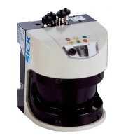
All TIC102 units are connected in series via Ethernet cables. Connection to the external
customer network is done using the TIC102 Master. The system components are each
supplied separately with voltage.
Fig. 83: Electrical installation – TIC102 wiring overview
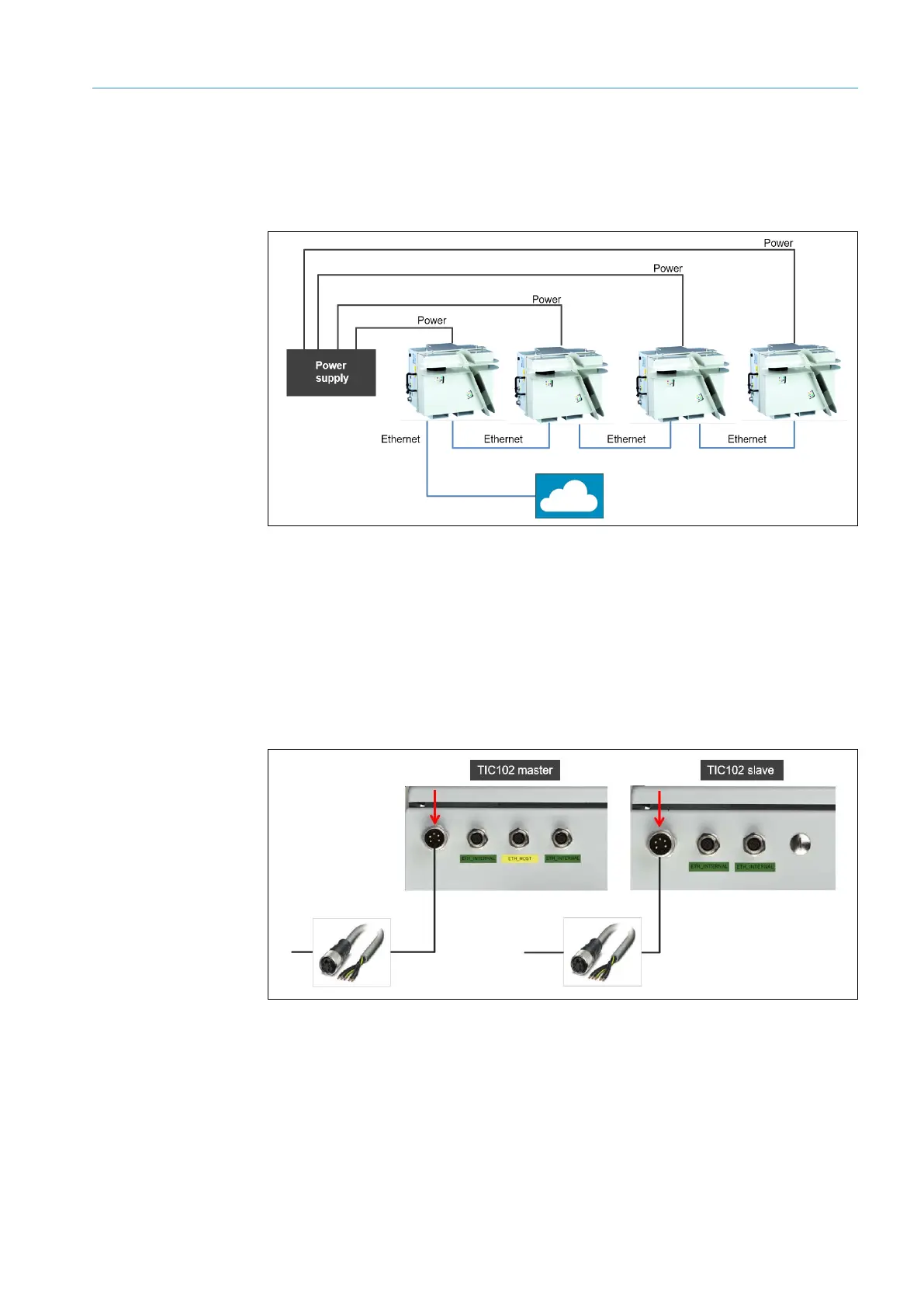
5.3.1 Connecting the TIC102 to the voltage supply
Connect the voltage to each TIC102. Use the cables available as accessories for
connecting to the power supply. One end of the cables has a M12 plug connector, the
other is open for connection to the voltage supply.
1. Screw the M12 round connector of the cable into the Power Supply female connector
on the respective TIC102.
Fig. 84: Electrical installation of the TIC102 – Connecting the voltage supply