Functional Description of the Connectors/Interfaces
:
40 Hardware Description CNC 0610510/12 CNC 61.00
8.2 Pin Assignment and Interfaces
8.2.1 General Information
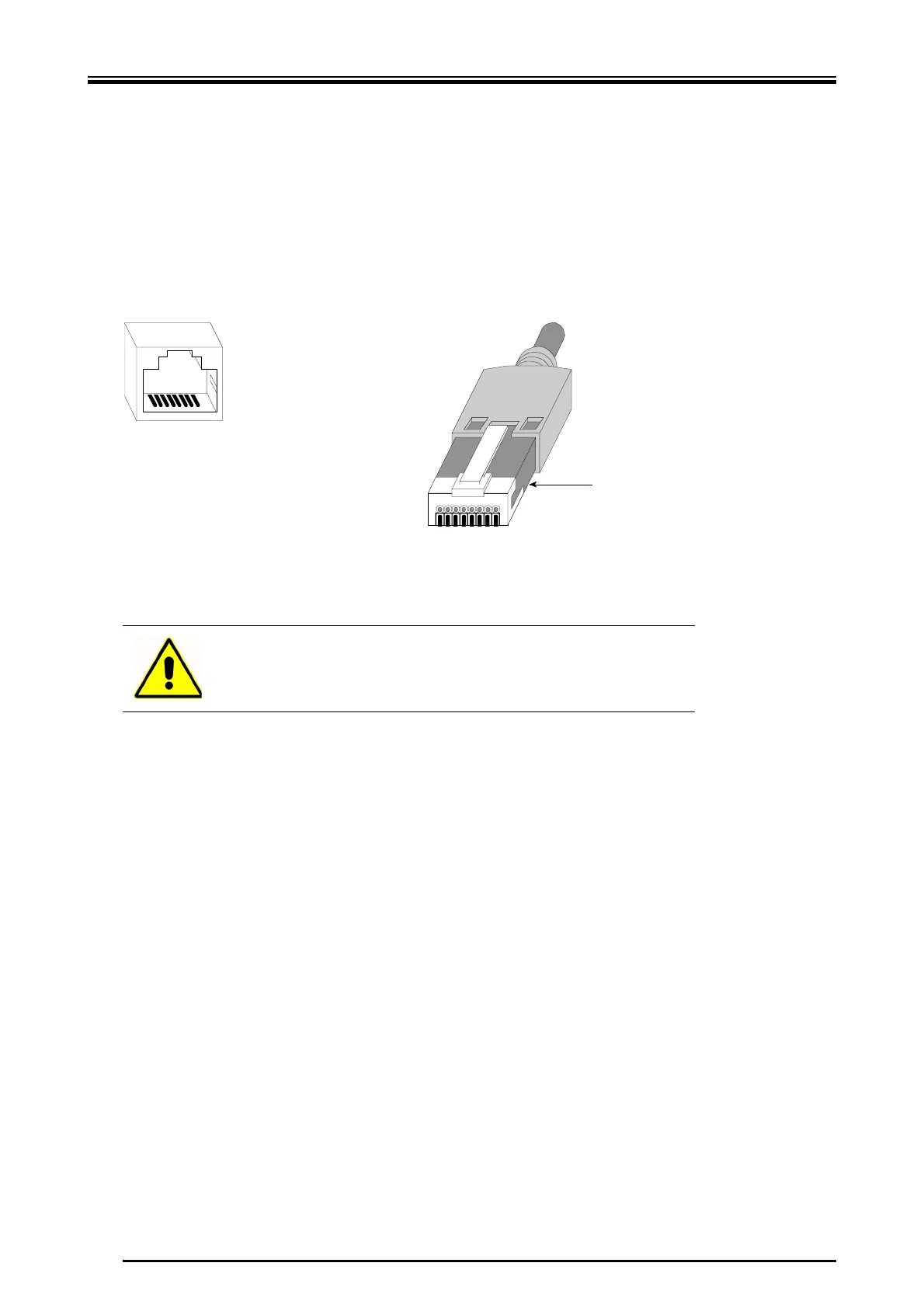
X RJ45 - connection with 8-pole female connector
In the following section, the male RJ45 connector and the female connector used for
SIEB & MEYER modules are shown.
For the connection, a shielded and twisted in pairs CAT5 cable of high quality must
be used.
8.2.2 X1 - Connection of Motor Measuring System (Feedback)
X 15-pole female Submin D connector
The shield must be connected to the metal shell of the 15-pole Submin D connector
and, if possible, to the motor connector.
Warning
Wires which are not used must be isolated when fabricating the ca-
ble. Otherwise, a short circuit may occur.
87654321
1234
567
8
Pin
Kabelschirm/
cable shield
 Loading...