:
Functional Description of the Connectors/Interfaces
CNC 61.00 Hardware Description CNC 0610510/12 57
8.3.6 Status Indication/Error Messages of Bus Systems - STX/
SRX/SRR
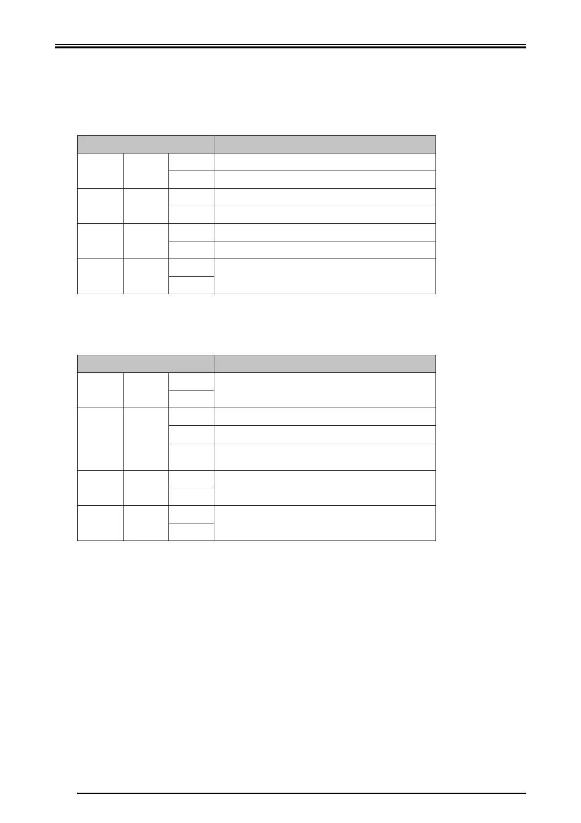
X Bus System MODLINK
X Bus System ETHERNET
8.3.7 Test Pins - MP/GND
between the measuring points MP and GND a voltage signal can be measured which
is proportional to the current speed value. This output can be useful in order to de-
termine the resonance behavior of the machine.
LED Meaning
STX green
D transmission signal is provided
E no transmission signal is provided
SRX green
D receiving signal is provided
E no receiving signal is provided
SRR orange
D transmission error
E no transmission error
* orange
D
no meaning
E
* LED has no designation
LED Meaning
STX green
D
no meaning
E
SRX green
D connection to the ETHERNET is provided
F input data
E no connection to the ETHERNET is provided (or wrong firm-
ware)
SRR orange
D
no meaning
E
* orange
D
no meaning
E
* LED has no designation
 Loading...