Option Modules
:
84 Hardware Description CNC 0610510/12 CNC 61.00
10.3.1 X11/X12 - INTERBUS
The Interbus interface expands the CNC 61.00 as remote bus participant in the In-
terbus. The interface occupies 4 words (64 bits) in the address range and is adjusted
to ID=3 (identification). The status of the bus is displayed by three LEDs on the front
panel of the module:
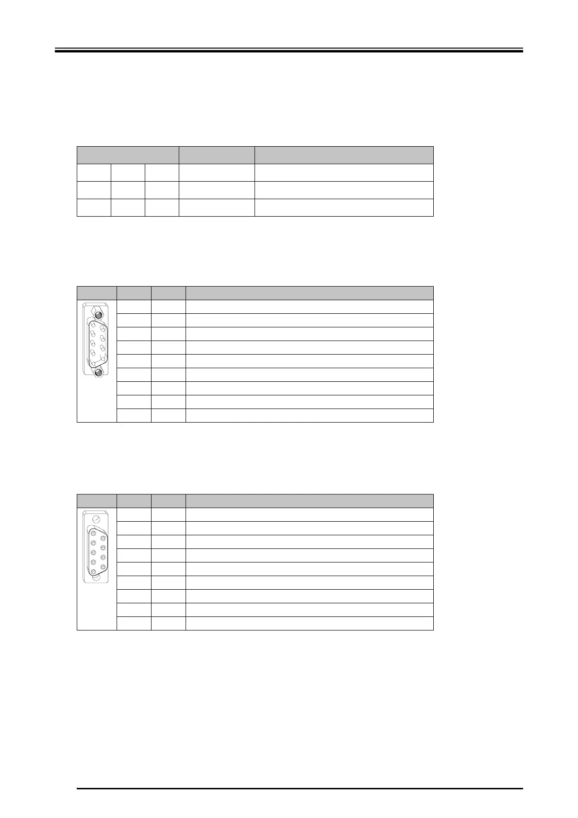
X12 - Interbus Input
X 9-pole male Submin D connector
X11 - Interbus Output
X 9-pole female Submin D connector
X Pin 5 serves for supplying pin 9; detection whether further modules will follow.
Further modules will follow if 5 V are applied to pin 9.
X Pin 5 and pin 9 not connected = no further modules;
Pin 5 and pin 9 connected = further modules
LED Designation Meaning
cc green 2 remote bus check monitoring of the remote bus cable of the input
ba green
2 active bus bus connection is completed
RD red
2 Error module error / no active master
Pin I/O Function
1ODO 1+
2IDI 1+
3GND
4
5
6ODO 1-
7IDI 1-
8
95V
Pin I/O Function
1ODO 2+
2IDI 2+
3GND
4
55V
6ODO 2-
7IDI 2-
8
9IRBST
5
9
1
6
1
5
6
9
 Loading...