:
Functional Description of the Connectors/Interfaces
CNC 61.00 Hardware Description CNC 0610510/12 45
8.2.5 Angle Pulse Inputs
The module permits connection of two incremental encoders (2./3. measuring sys-
tem) to the CNC 61.00. Incremental encoders with 5 V output level can be used. For
the 2./3. measuring system an external supply is required.
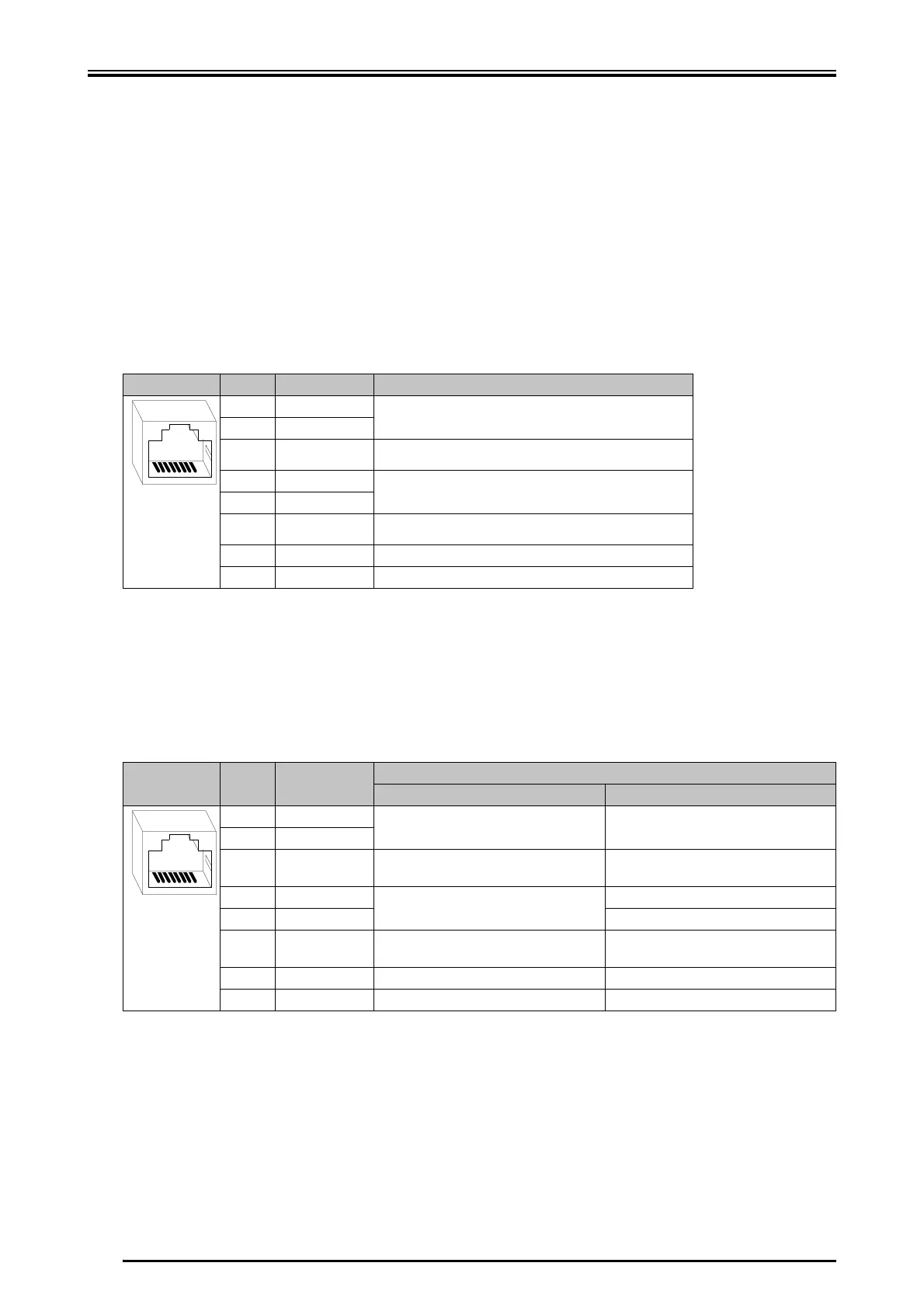
8.2.5.1 X4 - ENC1, Angle Pulse Input
X female RJ45 connector
8.2.5.2 X5 - ENC2 - Angle Pulse Input/SSI
X female RJ45 connector
Pin Designation Function
1UA1+
First differential signal pair
2UA1-
3 UB1+ In combination with UB1- second differential signal pair
shifted by 90°
4 UN1+
zero pulse
5 UN1-
6 UB1- In combination with UB1+ second differential signal pair
shifted by 90°
7 NC Not assigned
8 GND Ground
87654321
Pin Designation Function
Angle pulse input SSI
1UA2+
First differential signal pair First differential signal pair
2UA2-
3 UB2+ In combination with UB2- second differ-
ential signal pair shifted by 90°
In combination with UB2- second differ-
ential signal pair shifted by 90°
4 UN2+
Zero pulse
SSI data -
5 UN2- SSI data +
6 UB2- In combination with UB2+ second dif-
ferential signal pair shifted by 90°
In combination with UB2+ second dif-
ferential signal pair shifted by 90°
7 NC Not assigned Not assigned
8 GND Ground Ground
87654321
 Loading...