Functional Description of the Connectors/Interfaces
:
44 Hardware Description CNC 0610510/12 CNC 61.00
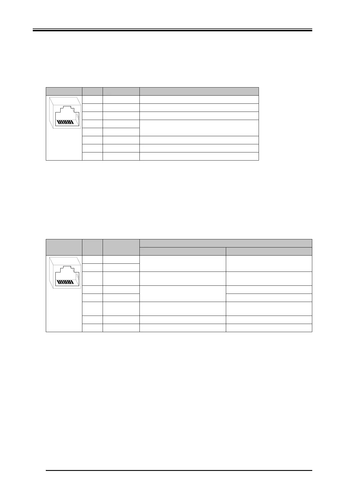
8.2.3 X2 - COM, Connection for Terminal or Programming Device
X female RJ45 connector
Regarding the levels the signals RxD, TxD, CTS and RTS correspond to the RS 232
specification.
8.2.4 X3 - ENCO, Angle Pulse Output/SSI
X female RJ45 connector
The module provides the angle pulses of the first measuring system externally. The
first measuring system is required if e.g. two axes must be synchronized (electronic
gear).
Pin Designation Function
1 TxD Transmit data: transmit data
2 RxD Receive data: receive data
3 CTS Clear to send: clear to send
4D+
RS 485 data bus
5D-
6 RTS Request to send: Transmitting unit ON
7 VCC Supply for terminating resistors
8 GND Ground
87654321
Pin Designation Function
Angle pulse output SSI
1UA0+
First differential signal pair First differential signal pair
2UA0-
3 UB0+ In combination with UB0- second differ-
ential signal pair shifted by 90°
In combination with UB0- second differ-
ential signal pair shifted by 90°
4 UN0+
Zero pulse
SSI clock -
5 UN0- SSI clock +
6 UB0- In combination with UB0+ second dif-
ferential signal pair shifted by 90°
In combination with UB0+ second dif-
ferential signal pair shifted by 90°
7 NC Not assigned Not assigned
8 GND Ground Ground
87654321
 Loading...