:
Functional Description of the Connectors/Interfaces
CNC 61.00 Hardware Description CNC 0610510/12 37
8 Functional Description of the Connectors/
Interfaces
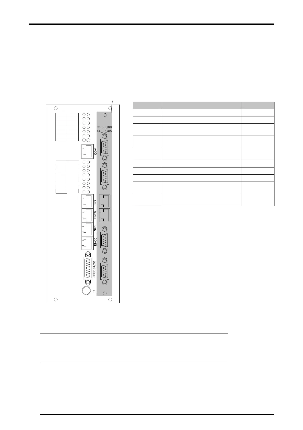
8.1 Front Panel 0610512
Connector Meaning Description
LEDs status indications page 54
pins measuring point page 57
X2 COM, connector for terminal or pro-
gramming device
page 44
LEDs for status indications of the inputs/out-
puts
page 51
X6 SIO, connector for serial input and output
modules
page 46
X5 angle pulse input, SSI page 45
X4 angle pulse input page 45
X3 ENCO, angle pulse output/SSI page 44
X1 Feedback, connector for the first motor
measuring system
page 40
ID switch coding selector for the axis address of
the module
page 58
* The front panels of the different option modules are shown in the chapter "Option modules“,
page 67. (The option modules are only available for the series 0610512, and are not available for
0610510).
L
According to the variant, the connectors and the assignment on the
slot of the option module can vary! The variant of the option module
must be specified when ordering the module. A later upgrading of the
individual option modules is not possible!
FC0 FC1
FC2
FC3
RIO RON
CNC
STX
SRR
MP
REM
SRX
GND
I0 O0
I1
O1
I2
O2
I3
I4
I5
I6
O3
O4
O6
I7
O5
O7
X2
X6
X5
X4
X3
X1
LEDs
Pins
X1
Module Slot -
Option Module*
 Loading...