:
Functional Description of the Connectors/Interfaces
CNC 61.00 Hardware Description CNC 0610510/12 49
8.2.9 X30 - Power Supply, X31/X32 Ballast Resistor
8.2.9.1 Connection Example for Three-Phase Supply with/without
Transformer
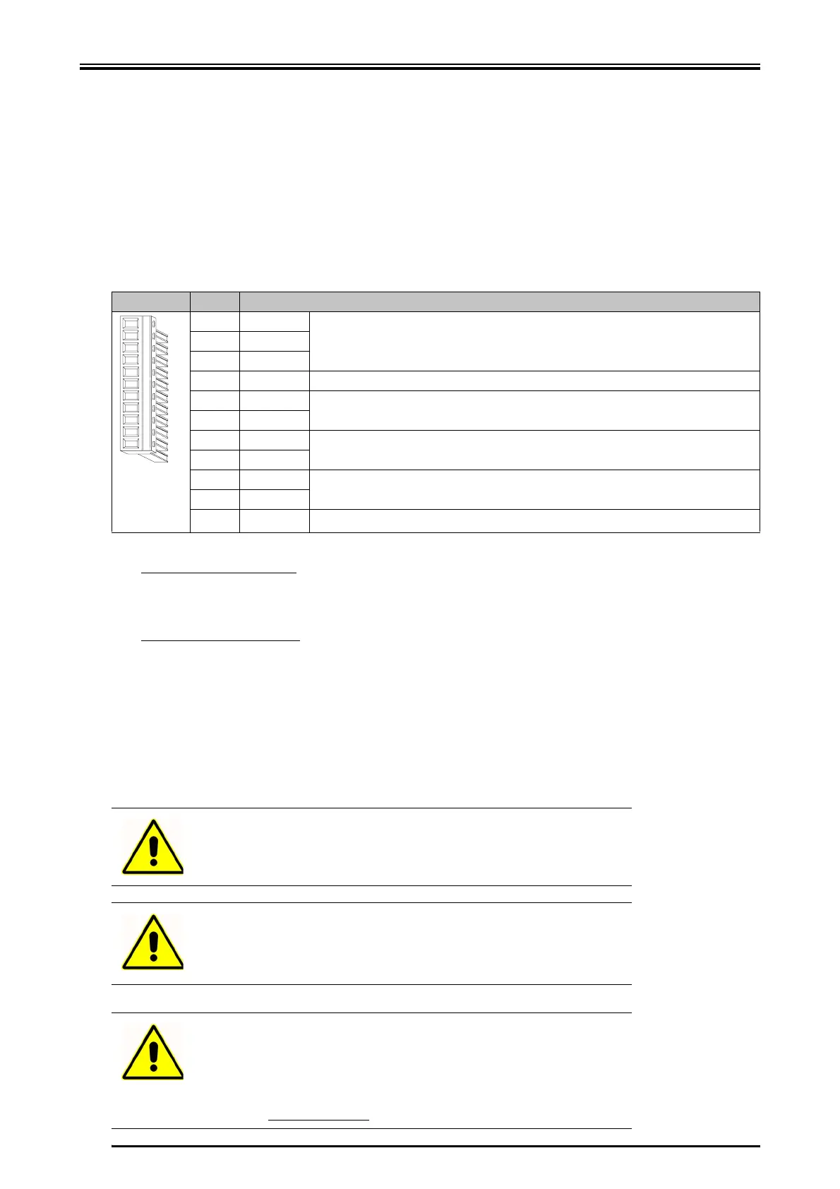
X 11 pole Power CombiCon
Pin Designation
1L1
Main voltage supply (see "Technical Data“, page 33)2L2
3L3
4 PE earth conductor
5 LL1
Logic voltage supply. The logic voltage supply must always be connected (same poten-
tial as main supply, see "Technical Data“ page 33)
6 LL2
7-UB
Intermediate circuit voltage !
8-UB
9+UB
Intermediate circuit voltage +
10 +UB
11 REX
External ballast resistor
1
1 Up to device version 001:
If an external ballast resistor is used, the fuse F1 on the power supply card 036050001 must be re-
moved (page 59). The external ballast resistor is connected between +UB and REX.
From device version 002:
X31/X32: switch-over for internal/external ballast resistor
wire bridge between X31 and X32 = internal ballast resistor active
wire bridge between X31 and X32 removed = external ballast resistor active
Adjustment of the ballast circuirt vie the jumpers J9/J10. The jumper can be accessed from the back
side of the device.
J9/J10 J9 plugged = internal ballast resistor (default state when devive is delivered)
J10 plugged = external ballast resistor
Warning
Please consider that an intermediate circuit voltage of up to 600 V
DC
may result!
Warning
For devices which are designed for a high power but low intermediate
circuit voltage, an autotransformer is required in order to reduce the
supply voltage.
Warning
The inputs LL1 and LL2 must always be connected. The angle puls-
es and error messages are kept in case of an EMERGENCY STOP
situation. If the main voltage supply is turned off, make sure that all
three mains phases are also turned off! For this reason a main con-
tactor with positively driven
contacts must be used.
 Loading...