Option Modules
:
70 Hardware Description CNC 0610510/12 CNC 61.00
Pin assignment
X 9-pole female Submin D connector
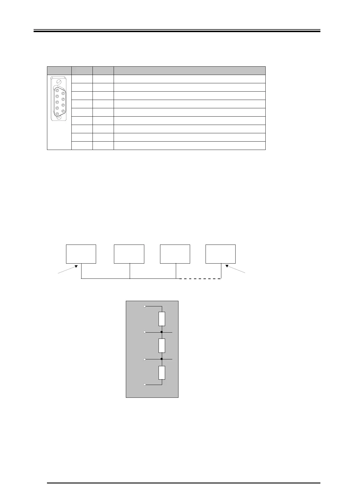
10.1.2.1 Bus Termination
The Profibus must be terminated electrically in order to prevent interferences. For
this reason each bus "participant" permits "passive" termination of the bus (see figure
below). Usually, this terminal is integrated into the connector of the cable of the Profi-
bus (connectors from ERNI or SIEMENS) and must be provided at both "sides" of the
bus.
Pin I/O Function
1 Shield
2
3 I/O RxD/TxD-P (B)
4 O Request to send
5 Reference ground for the terminal of the bus
6 Supply voltage of 5 volts for the terminal of the bus
7
8 I/O RxD/TxD-N (A)
9
1
5
6
9
390 S
220 S
390 S
Pin 6
Pin 5
Pin 3
Pin 8
Master
CNC61
CNC61 CNC61
Busabschluss Busabschluss
z. B. SPS, PC
Stecker für den
Busabschluss
 Loading...