Functional Description of the Connectors/Interfaces
:
50 Hardware Description CNC 0610510/12 CNC 61.00
8.2.9.2 Connection Example for Single-Phase Supply up to max.
230 V
AC
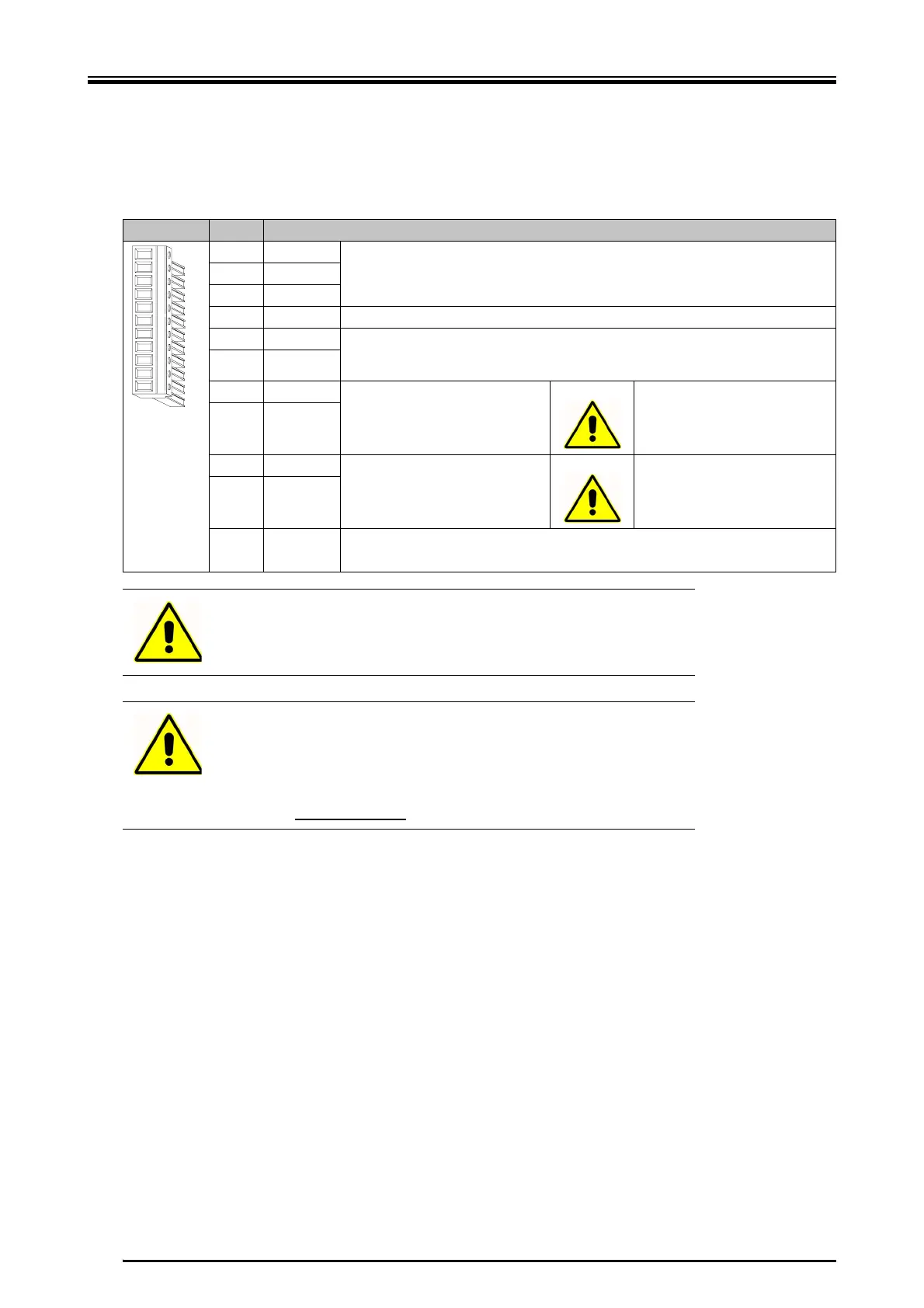
X 11 pole Power CombiCon
Pin Designation
1N
Main voltage supply (see "Technical Data“, page 33)2L1
3-
4 PE earth conductor
5 NN1 Logic voltage supply. The logic voltage supply must always be connected. The phase
position must coincide with the phase position of the main voltage supply!
(see "Technical Data“, page 33).
6 LL1
7-UB
Intermediate circuit voltage -
High d.c. voltage
is generated!
8-UB
9+UB
Intermediate circuit voltage +
High d.c. voltage
is generated!
10 +UB
11 RE
External ballast resistor. This must not be lower than 22 Ω
. If required, the external bal-
last resistor is connected between +UB and RE.
Warning
Please consider that an intermediate circuit voltage of up to 300 VDC
may result!
Warning
The inputs NN1 and LL1 must always be connected. The angle puls-
es and error messages are kept in case of an EMERGENCY STOP
situation. If the main voltage supply is turned off, make sure that all
three mains phases are also turned off! For this reason a main con-
tactor with positively driven
contacts must be used.
 Loading...