:
Functional Description of the Connectors/Interfaces
CNC 61.00 Hardware Description CNC 0610510/12 43
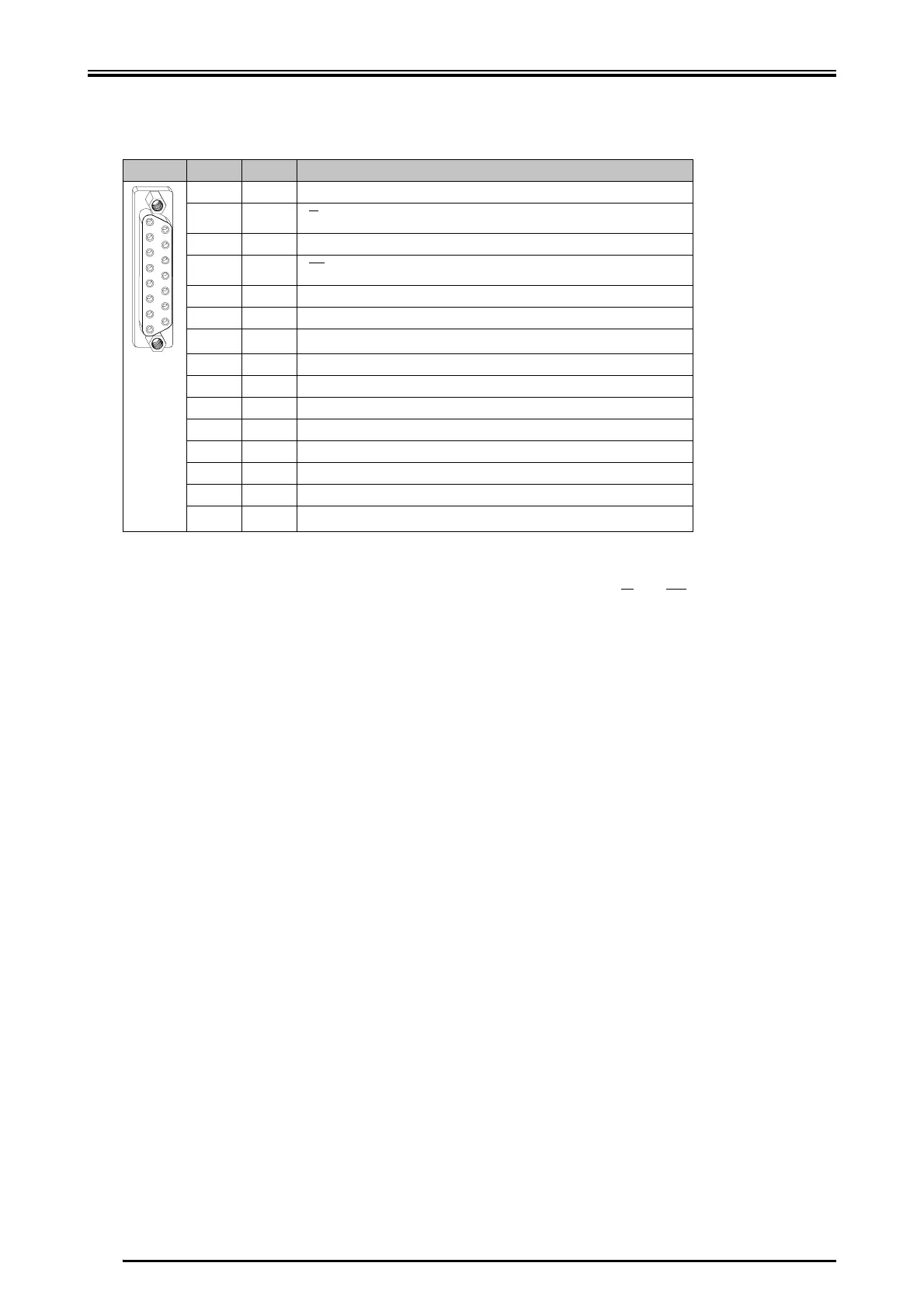
8.2.2.3 Optical or Magnetical Length Measuring System
Use a shielded cable with six leads, each 2 must be twisted. Twist mode: /0°, /
90°, ref.+/ref.- and +5 V/0 V. If the thermal contact is evaluated, a shielded twisted
pair cable with 5 pairs of wires must be used.
For incremental encoders without difference voltage signal, the pins 9 and 11 must
be supplied with 5 V (pin 8).
Connect the shield with largest surface to the connector shell.
Pin I/O Function
1O0 V
2I
3O0 V
4I
5O0 V
6 O Ref.-
7I
thermal motor protection
1
8O+5 V
9I0°
10 O 0 V
11 I 90°
12 O 0 V
13 O Ref.+
14 O 0 V
15 O
thermal motor protection
1
1
If no thermal motor protection is connected, pin 15 and pin 7 must be bridged.
1
8
9
15
0°
90°
0° 90°
 Loading...