:
Functional Description of the Connectors/Interfaces
CNC 61.00 Hardware Description CNC 0610510/12 41
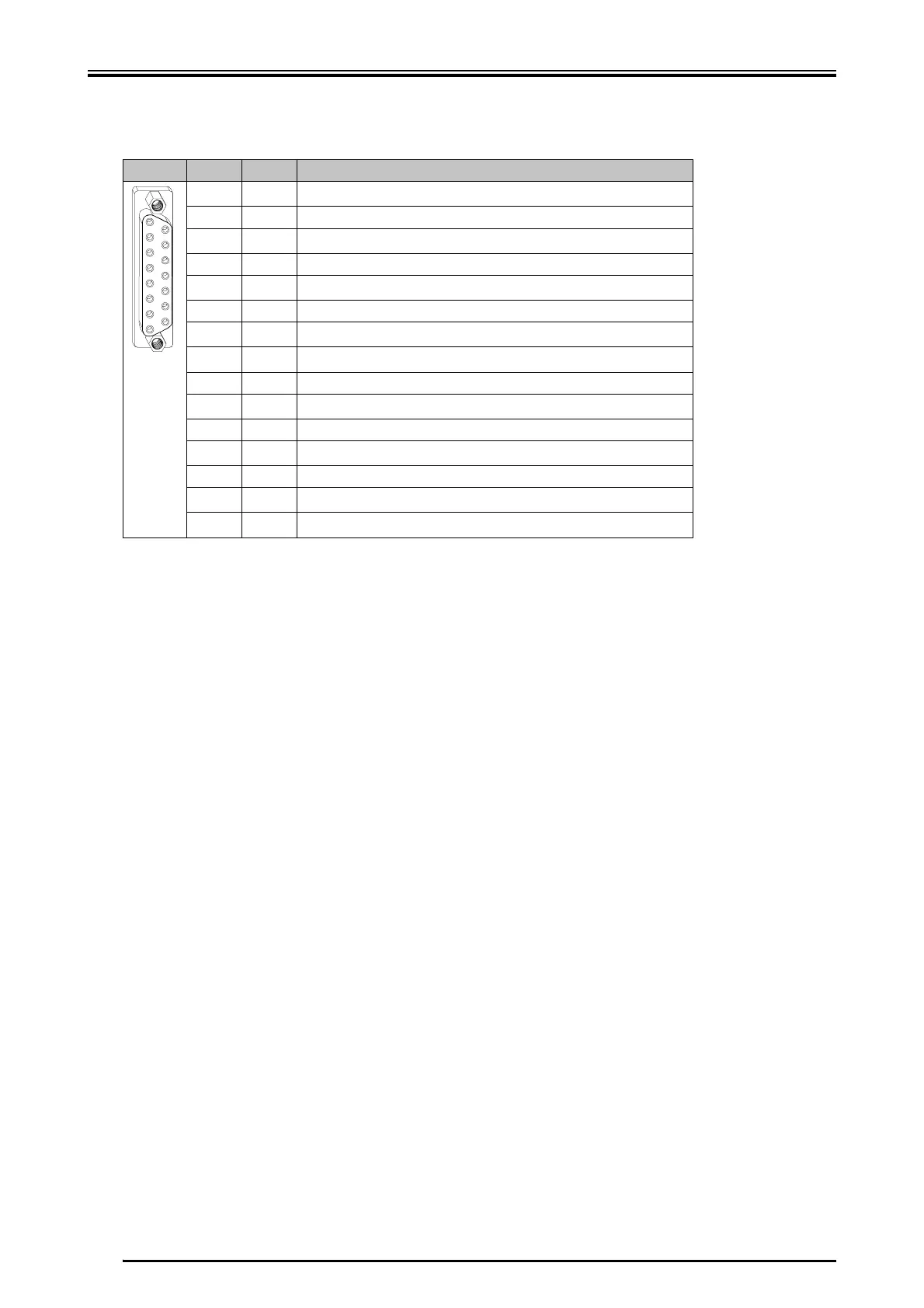
8.2.2.1 Resolver Evaluation
Use a shielded cable with six leads, each 2 must be twisted. Twist mode: sine/sine,
cosine/cosine, rotor/rotor; designation of the line, e.g. LIYCY 3 × 2 × 0.14. If the ther-
mal contact is evaluated a shielded cable with 8 leads (4x2 twisted-pairs of wires)
must be used.
Pin I/O Function
1O
0 V
1
2IS1 sine
3
0 V
1
4IS4 cosine
5
0 V
1
6 O R3 rotor
7I
thermal motor protection
2
8
0 V
1
9IS3 sine
10
0 V
1
11 I S2 cosine
12
0 V
1
13 O R1 rotor
14
0 V
1
15 O
thermal motor protection (24 V)
2
1
is connected to GND by the servo amplifier
2
If no thermal motor protection is connected, pin 15 and pin 7 must be bridged.
1
8
9
15
 Loading...