Functional Description of the Connectors/Interfaces
:
46 Hardware Description CNC 0610510/12 CNC 61.00
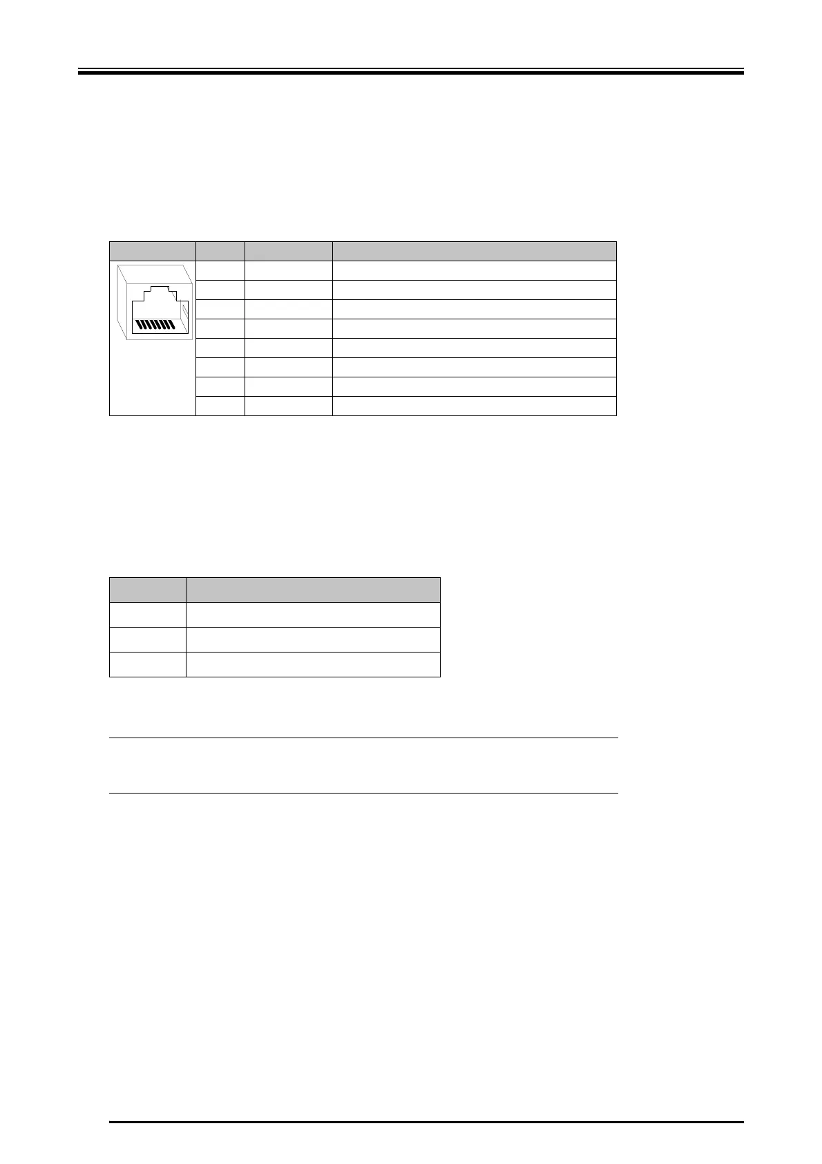
8.2.6 X6 - SIO, I/O Expansion
X female RJ45 connector
The module provides a connector for an I/O expansion of additional 128 inputs and
outputs. The I/O expansion interface establishes the connection to the following ba-
sic module. Further input modules and output modules can be connected to the men-
tioned modules in any order.
8.2.7 Connection to the Bus System
The connectors for the connection of the bus system are on the bottom side of the
module. These female connectors provide different connection possibilities (double
assignment), e.g. CAN bus, MODLINK, Ethernet etc.
Pin Designation Function
1 DO+ Data Out+ = positive data output signal
2 DO- Data Out- = negative data output signal
3 CLK+ Clock+ = positive clock signal
4 LD + Load Data+
5 LD – Load Data-
6 CLK - Clock- = negative clock signal
7 DI+ Data In+ = positive data input signal
8 DI- Data In- = negative data input signal
87654321
Connector Possible connections
X7 MODLINK, ETHERNET, CAN
X8 MODLINK, CAN
X9 CAN, analog input
View of the module, see page 22
L
The desired bus system must be specified when ordering the mod-
ule. A later upgrading of the option module is not possible!
 Loading...