Functional Description of the Connectors/Interfaces
:
42 Hardware Description CNC 0610510/12 CNC 61.00
8.2.2.2 Hall Effect Sensor Evaluation
Use a shielded cable. Connect the shield with largest surface to the connector shell.
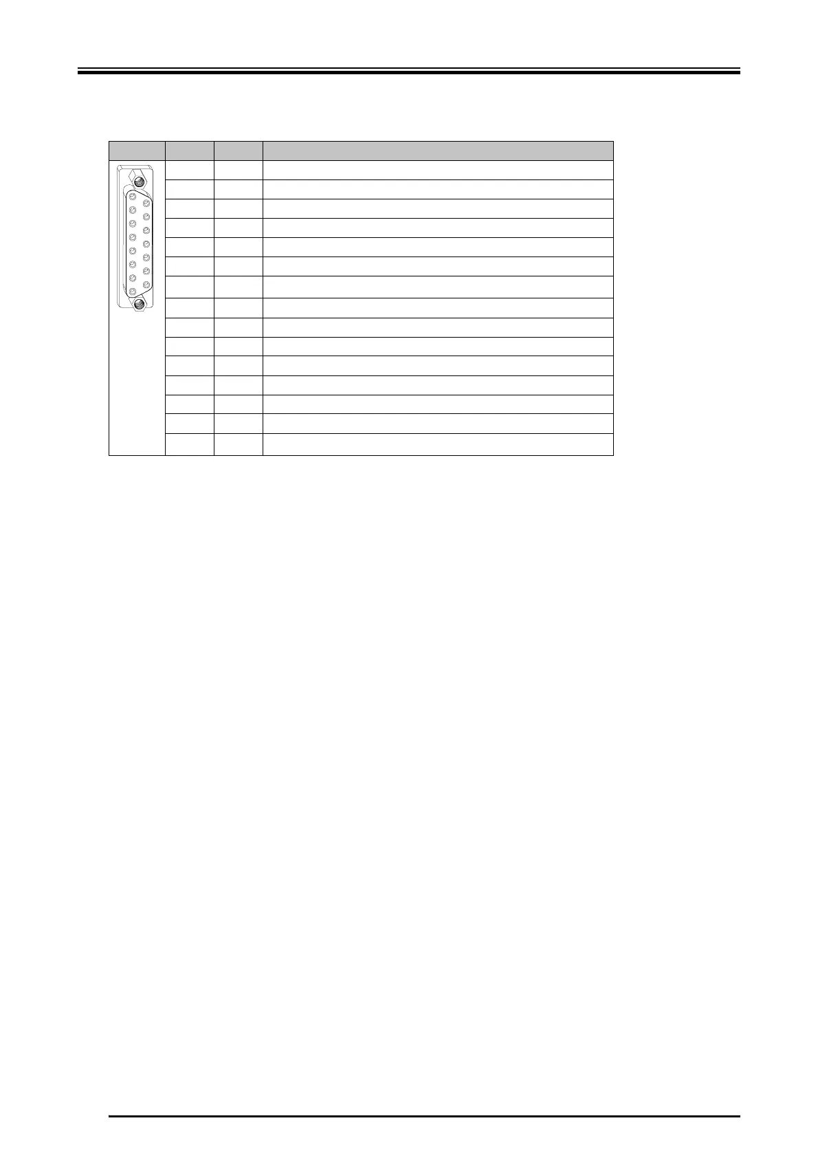
Pin I/O Function
1O0 V
2 I sensor A
3 not to be connected
4 not to be connected
5 not to be connected
6n.c.
7I
thermal motor protection
1
8OGND
9 I sensor C
10 I sensor B
11 not to be connected
12 not to be connected
13 O +24 V for Hall effect sensor
14 O GND
15 O
thermal motor protection (24 V)
1
1
If no thermal motor protection is connected, pin 15 and pin 7 must be bridged.
1
8
9
15
 Loading...