Addressing
S7-300 Programmable Controller Hardware and Installation
7-2 A5E00105492-01
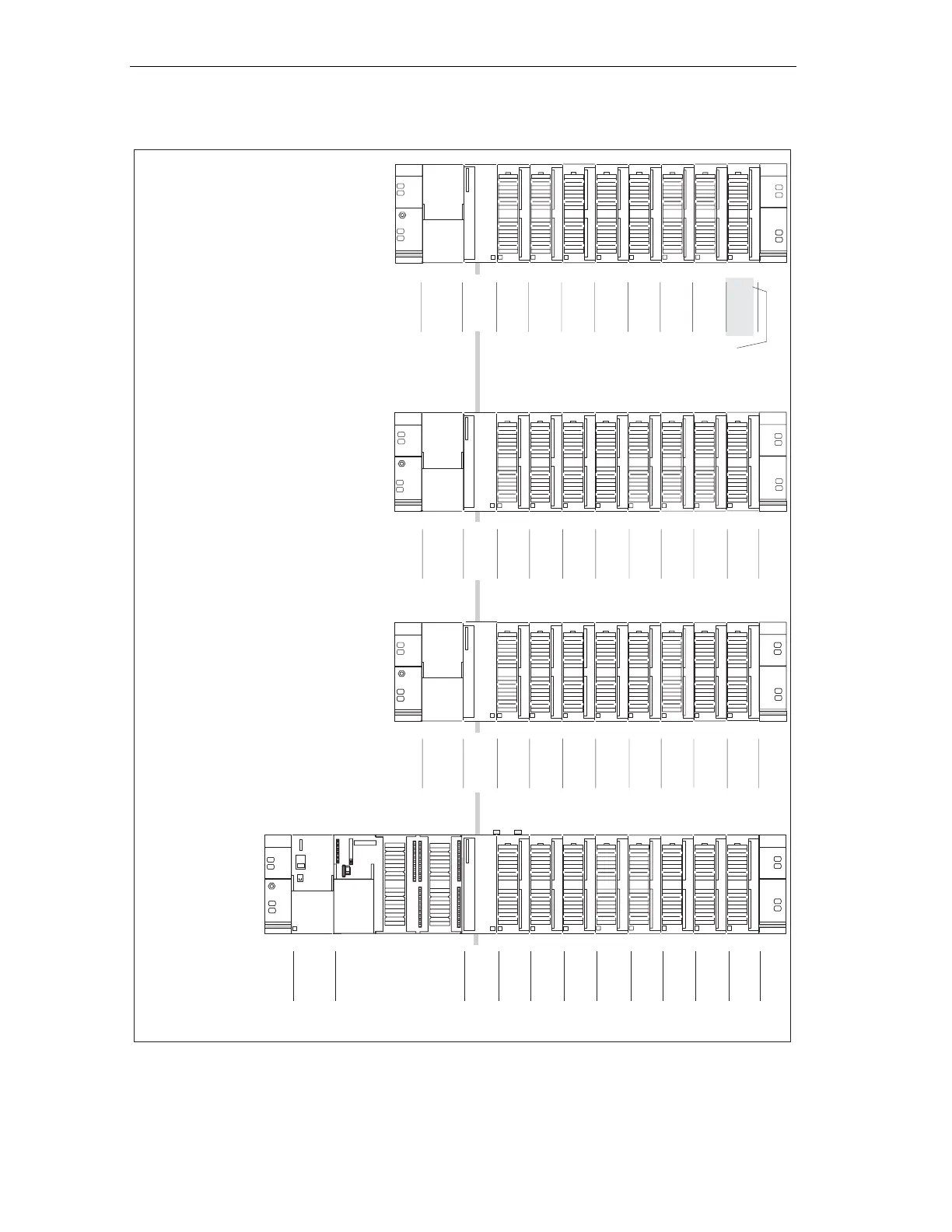
Rack 2
(EG)
Rack 1
(EG)
Rack 3
(EG)
Rack 0
(ZG)
1
2
3
4
0IM
5
4
256 272
6
8
288
7
12
304
8
16
320
9
20
336
10
24
352
11
28
368
slot number
BG digitalinitial address
BG e analoginitial address
4
4
4
3
3
3
IM
IM
IM
32
64
96
5
5
5
36
68
100
384
512
640
400
528
656
6
6
6
40
72
104
416
544
672
7
7
7
44
76
108
432
560
688
8
8
8
48
80
112
448
576
704
9
9
9
52
84
116
464
592
720
10
10
10
56
88
120
480
608
736
11
11
11
60
92
124
496
624
752
slot number
slot number
slot number
BG digitalinitial address
BG digitalinitial address
BG initial address digital
BG analoginitial address
BG analoginitial address
BG-Anfangsadresse analog
not with
CPU 314 IFM/
CPU 31xC
124 (CPU 31xC)*
752 (CPU 31xC)*
* see chapter “Addressing the integrated inputs and outputs of the CPU”
SF
BUSF
DC5V
FRCE
RUN
STOP
SIEMENS
Figure 7-1 S7-300 slots and the corresponding module start addresses
 Loading...


