Testing functions, Diagnostics and Fault Elimination
S7-300 Programmable Controller Hardware and Installation
10-12 A5E00105492-01
10.6 Diagnostics of DP CPUs
10.6.1 Diagnostics of DP CPUs operating as DP master
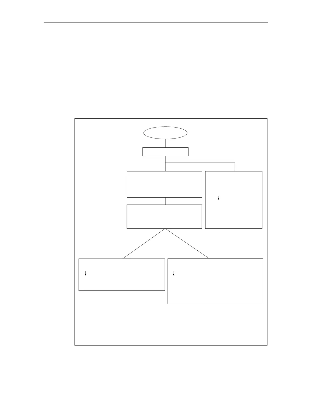
Diagnostics evaluation in the user program
The figure below shows you the procedure for evaluating the diagnostics in the
user program.
Diagnostic event
OB82 is called
Enter Bit 0 of the
as Bit 15 in the
OB82_IO_FLAG
OB82_MDL_ADDR
Result: diagnostic address
“OB82_MDL_ADDR*”
Read out OB82_MDL_ADDR
and
Read out
(= identifier I/O module)
OB82_IO_FLAG
For the diagnosis of the
components involved:
SFB 54call
(in DPV1 environment)
MODE =1 set
Diagnostic data is entered
in the TINFO and
AINFO parameters.
Note:
The SFC 13 is asynchronous, i. e. It can
be called several times if necessary until
it changes into the BUSY = 0 status.
First call in OB82,
Finish processing in the cycle.
For the diagnosis of the whole DP slave:
SFC 13call
Enter the diagnostic address
“OB82_MDL_ADDR*” in the
LADDR parameter
For the diagnosis of the modules involved:
SFC 51call
Enter the diagnostic address
“OB82_MDL_ADDR*” in the
Enter the SZL_ID
p (= diagnostic data of a module)
INDEX parameter
ID W#16#00B3 in the
arameter
318-2-DP>=V3.0.0
Figure 10-3 Diagnostics with CPU 31x-2 (315-2-DP as of 315-2AF03)
 Loading...


