Configuring
S7-300 Programmable Controller Hardware and Installation
4-40 A5E00105492-01
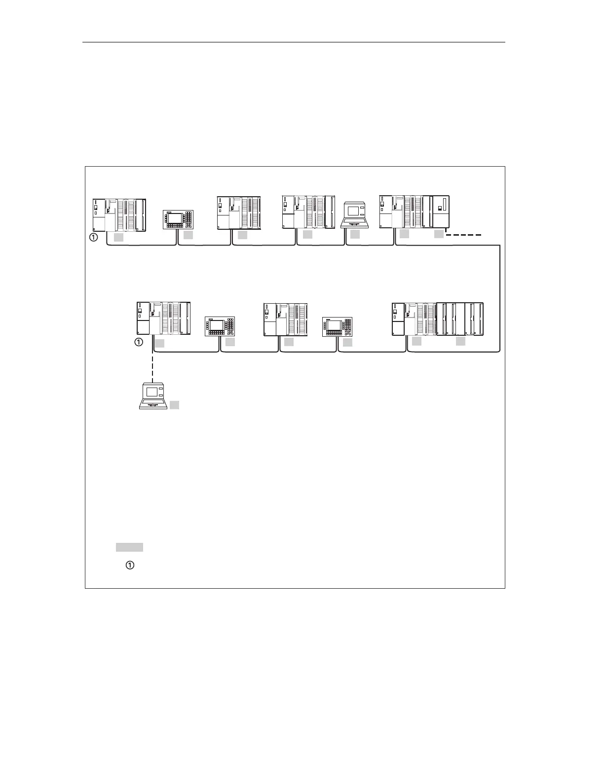
4.10.6 Network samples
Example: MPI subnet
The figure below shows you the block diagram of an MPI subnet.
0 ... x
0
PG*
12
OP 27
10
OP 27
5
PG
1
OP 27**
*Connected via spur lines for commisioning/maintenance only
(with default MPI address).
** connected to the MPI subnet later (with default MPI address).
*** the CP also has a PROFIBUS address in addition to the MPI address ( address 7 here).
**** In the case of the CPU 318-2 DP, the FMs/CPs do not have their own MPI address. In the case
of the S7 300 CPUs, (without CPU 318-2 DP) you can also allocate MPI addresses as you wish.
MPI addresses of nodes
Terminating resistance on
S7-300
3
SF
BUSF
BUSF
DC5V
FRCE
RUN
STOP
SIEMENS
S7-300
11
SF
BUSF
DC5V
FRCE
RUN
STOP
SIEMENS
S7-300**
2
SF
BUSF
DC5V
FRCE
RUN
STOP
SIEMENS
S7-300
4
SF
BUSF
DC5V
FRCE
RUN
STOP
SIEMENS
S7-300
13
SF
BUSF
DC5V
FRCE
RUN
STOP
SIEMENS
S7-300
6
CP****
7
PROFI-
BUS-
Subnetwork
SF
BUSF
DC5V
FRCE
RUN
STOP
SIEMENS
S7-300
9
FM****
8
SF
BUSF
DC5V
FRCE
RUN
STOP
SIEMENS
Figure 4-14 Example of an MPI subnet
 Loading...


