Configuring
S7-300 Programmable Controller Hardware and Installation
4-6 A5E00105492-01
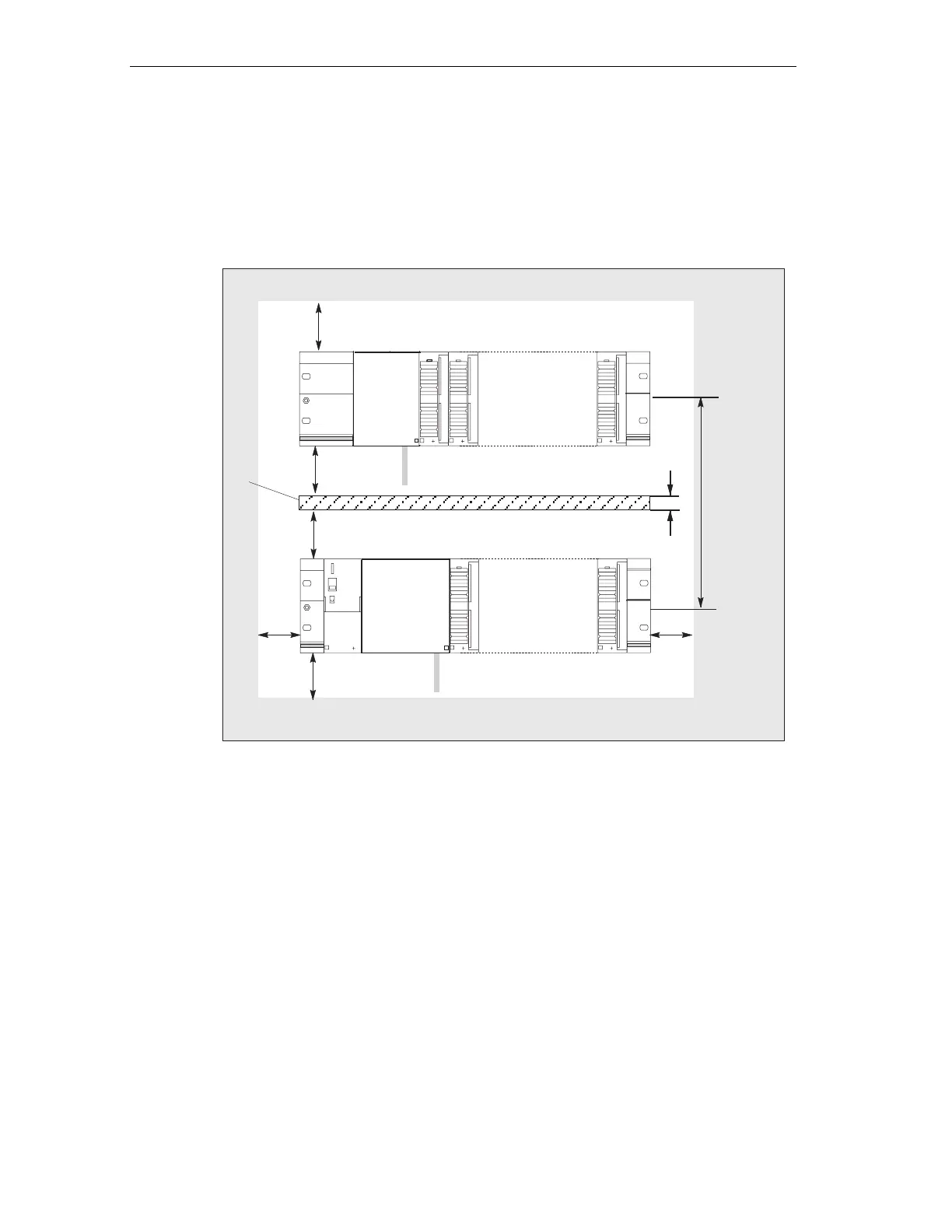
Rules: Clearance
You must maintain the clearance as shown in the figure in order to provide module
installation space and to ensure elimination of heat generated by the modules.
The S7-300 assembly on multiple module racks shown in the figure below specifies
the clearance between module racks and adjacent components, cable ducts,
cabinet walls etc.
40 mm
20 mm
40 mm
a
200 mm + a
CPU
CPU
40 mm (when using a shield contact element from its
lower edge)
40 mm
20 mm
e. g. cable channel
Figure 4-3 Clearance
 Loading...


