Configuring
S7-300 Programmable Controller Hardware and Installation
A5E00105492-01
4-27
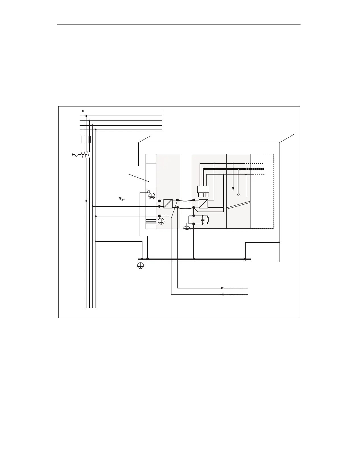
Example: S7-300 with load power supply unit from PS 307
The figure below shows the overall S7-300 configuration (load power supply unit
and grounding conception), with TN-S mains supply.
Apart from powering the CPU, the PS 307 also supplies the load current for the 24
VDC modules.
Note: The arrangement displayed does not correspond with the physical
arrangement; it was merely selected to give you a clear overview.
N
M
L1
M
PS
S7 300 CPU
µP
L1
L2
L3
N
PE
SM
Rail
Low-voltage distribution
e. g. TN-S System (3 x 400 V)
Ground bus
in cabinet
load circuit DC 24 V for
DC modules
L+
signal modules
Cabinet
Figure 4-13 Example: S7-300 with load power supply from PS 307
 Loading...


