Configuring
S7-300 Programmable Controller Hardware and Installation
4-10 A5E00105492-01
Rules: Interference-proof installation of the connection
Special shielding and grounding measures are not required if you interconnect the
CU and ED using suitable interface modules (Send IM and Receive IM). However,
make sure that
• all module racks are interconnected with low impedance,
• the module racks of a grounded assembly are grounded in a star pattern,
• the contact springs of the module racks are clean and not bent in order to
ensure interference current diversion.
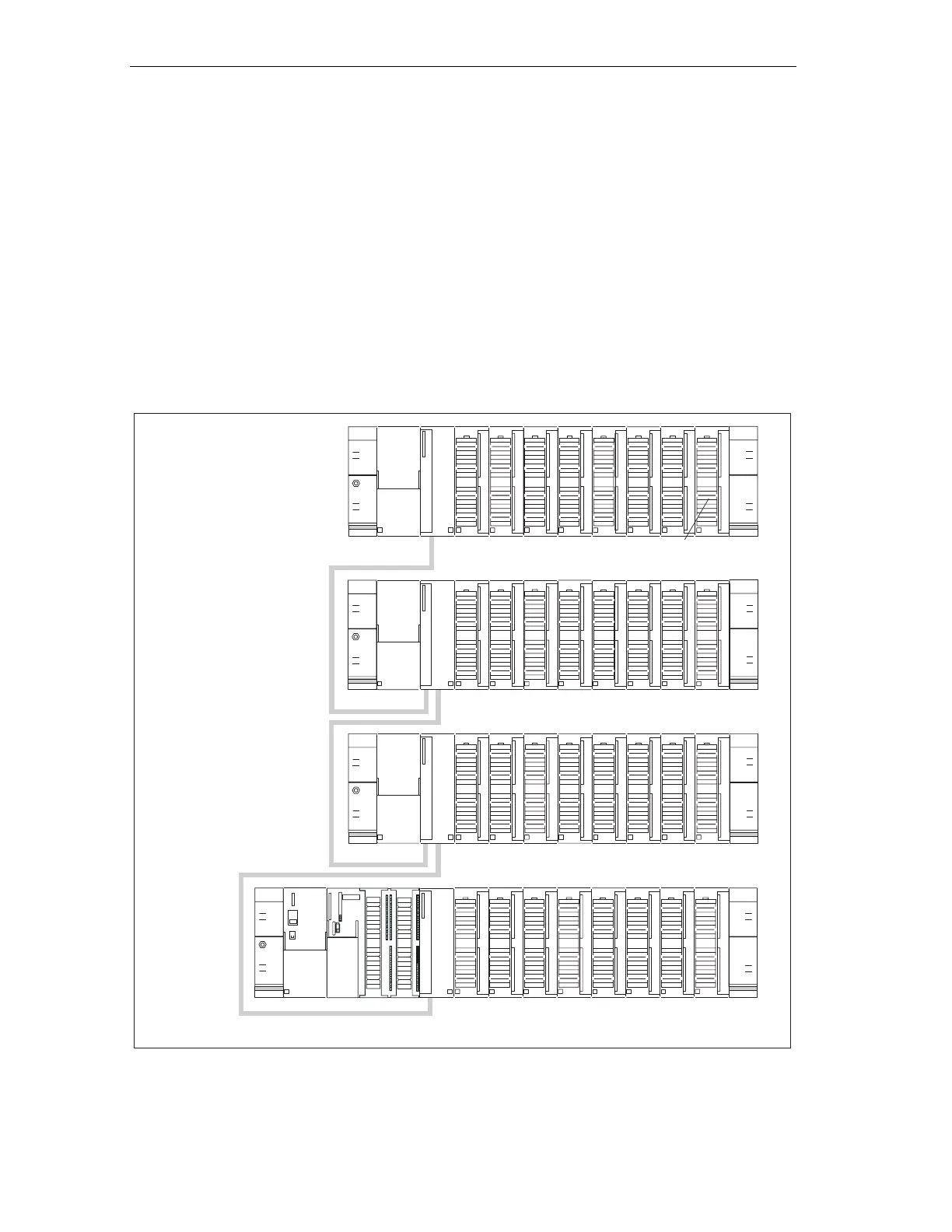
Example of a full assembly
The figure shows the arrangement of modules in an S7-300 assembly on 4 module
racks.
PS CPU SMsIM
Connecting cable 368
Rack 0
(ZG)
Rack 1
(EG)
Rack 2
(EG)
Rack 3
(EG)
IM
Connecting cable 368
IM
Connecting cable 368
IM
Not with
CPU 314 IFM/CPU 31xC
Figure 4-5 Full assembly
 Loading...


