Wiring
S7-300 Programmable Controller Hardware and Installation
6-10 A5E00105492-01
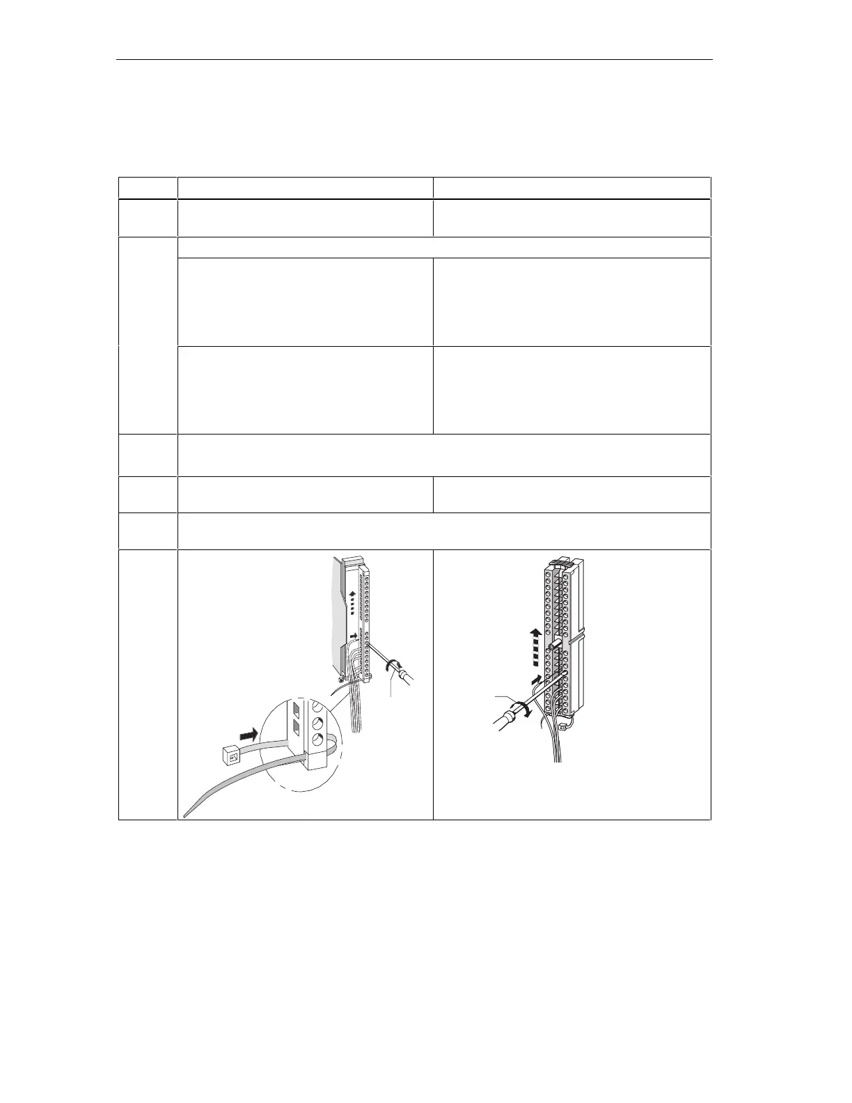
Wiring the front connector
Table 6-6 Wiring front connectors
Step 20-pin front connector 40-pin front connector
1. Thread the cable strain relief into the front
connector.
–
Do you want to exit the cables at the bottom of the module?
If yes:
Starting at terminal 20, work your way down
to terminal 1.
Starting at terminal 40 or 20, wire the connector,
working in alternating passes from terminals 39,
19, 38, 18 etc.until you have reached
terminals 21 and 1.
2.
If not:
Starting at terminal 1, work your way up to
terminal 20.
Starting at terminal 1 or 21, wire the connector,
working in alternating passes from terminals 2,
22, 3, 23 etc.until you have reached
terminals 20 and 40.
3. Front connectors with screw terminals:
Screw-tighten unused terminals also.
4. – Attach the cable strain-relief assembly around
the cable and the front connector.
5. Pull the cable strain-relief assembly tight. Push in the strain relief retainer to the left to improve
utilization of the available cable space.
–
1
2
0.5 Nm to
0.8 Nm
1
2
4
3
0.4 Nm to
0.7 Nm
 Loading...


