Maintenance
S7-300 Programmable Controller Hardware and Installation
9-8 A5E00105492-01
Simply push out the front connector coding with a screwdriver.
This upper part of the coding key must then be plugged back into the old module.
Putting a New Module into Service
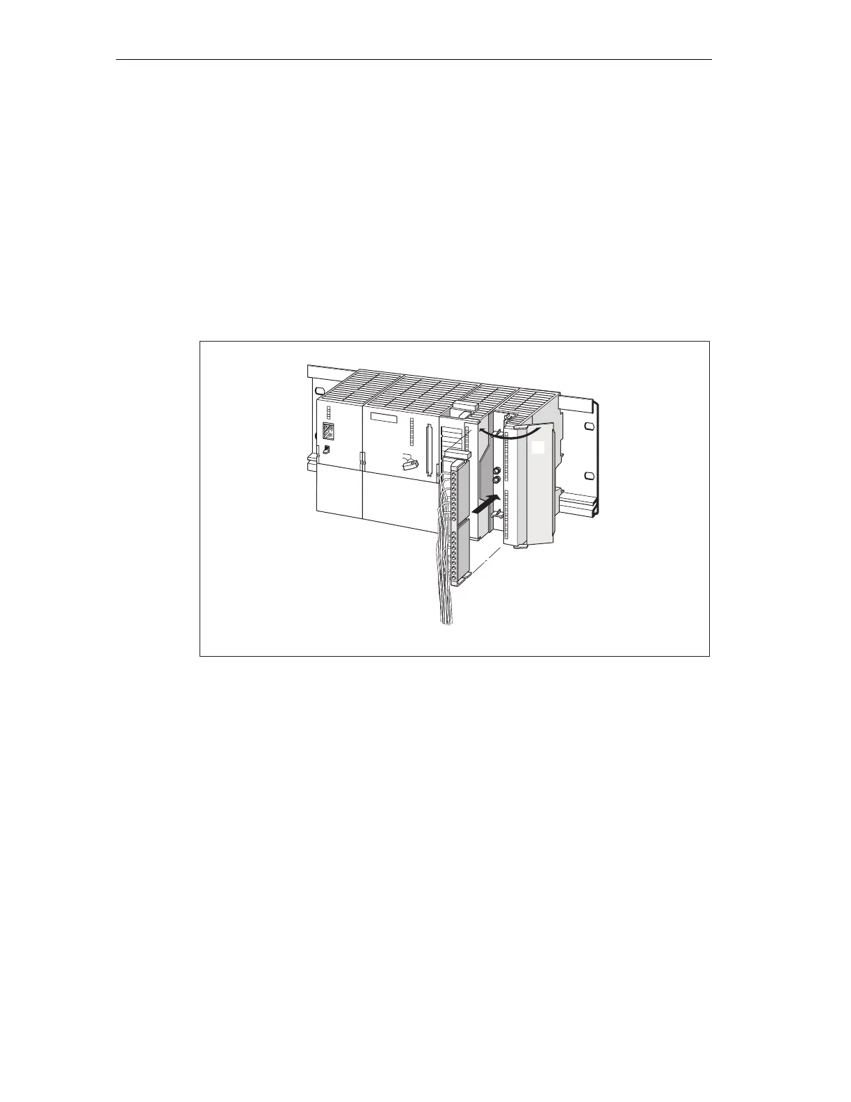
Proceed as follows to put the new module into service:
1. Open the front panel.
2. Reinstall the front connector.
3. Close the front panel.
4. Switch the load voltage back on.
5. Set the CPU to RUN mode again.
3
2
Figure 9-4 Inserting the front connector
Behavior of S7-300 after module replacement
After module replacement the CPU switches to run mode, provided no error has
occurred. If the CPU maintains STOP status, you can view the cause of error with
STEP 7 (refer to the STEP 7 User Manual).
9.5 Replacing the backup/rechargeable battery (not CPU 312 IFM
and CPUs 31xC)
Replacing the backup battery or the rechargeable battery
Always replace the backup/rechargeable battery in POWER ON state of the CPU,
in order to avoid data loss in internal memory or stopping the real-time clock.
 Loading...


