Wiring
S7-300 Programmable Controller Hardware and Installation
6-14 A5E00105492-01
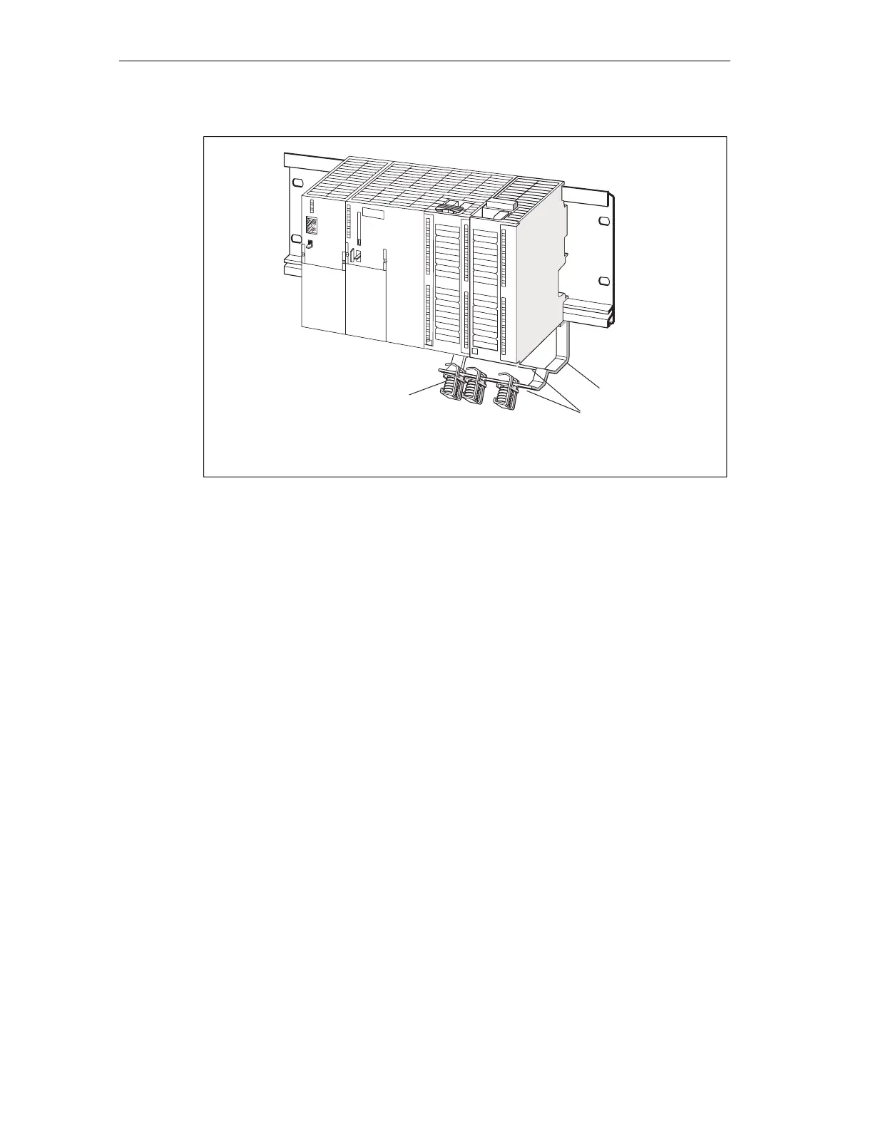
Shield terminal
Fixing bracket
Edge a
Figure 6-6 Shielding contact element underneath two signal modules
Terminating cables
Only one or two shielded cables can be terminated per shielding terminal (see the
figure below). The cable is clamped in at the stripped cable shielding.
1. Strip the cable shielding to a length of at least 20 mm.
2. Clamp in the stripped cable shielding underneath the shielding contact clamp.
Push the shielding clamp towards the module (1) and feed the cable through
underneath the clamp (2).
If you need more than four shielding terminals, start wiring at the rear row of the
shielding contact element.
 Loading...


