Configuring
S7-300 Programmable Controller Hardware and Installation
A5E00105492-01
4-19
N
L1
L+
M
PS
S7-300 CPU
µP
L1
N
M
external
L+
U
internal
M
internal
Data
L1
N
DI
DO
PE
Ground bus in
cabinet
AC 230 V load
power supply
DC 24 V load power supply
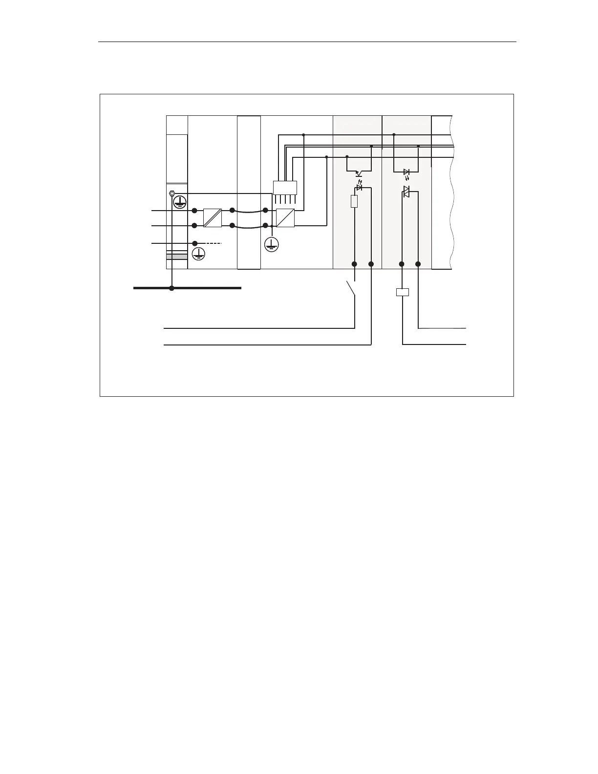
* In the case of CPU 31xC or 312 IFM, the connection is automatically established.
*
Figure 4-9 Configuration with isolated modules
Non-isolated modules
In configurations with non-isolated modules, the reference potentials of the control
circuit (M
internal
) and load circuit (
M
external) are not electrically isolated (see the
figure below ).
Example:
For operation with an SM 334 AI 4/AO 2 analog I/O module you must connect one
of the grounding terminals M
analog
to the CPU's chassis ground.
The figure below shows a sample configuration of an S7-300 CPU with non-
isolated modules.
 Loading...


