Addressing
S7-300 Programmable Controller Hardware and Installation
A5E00105492-01
7-5
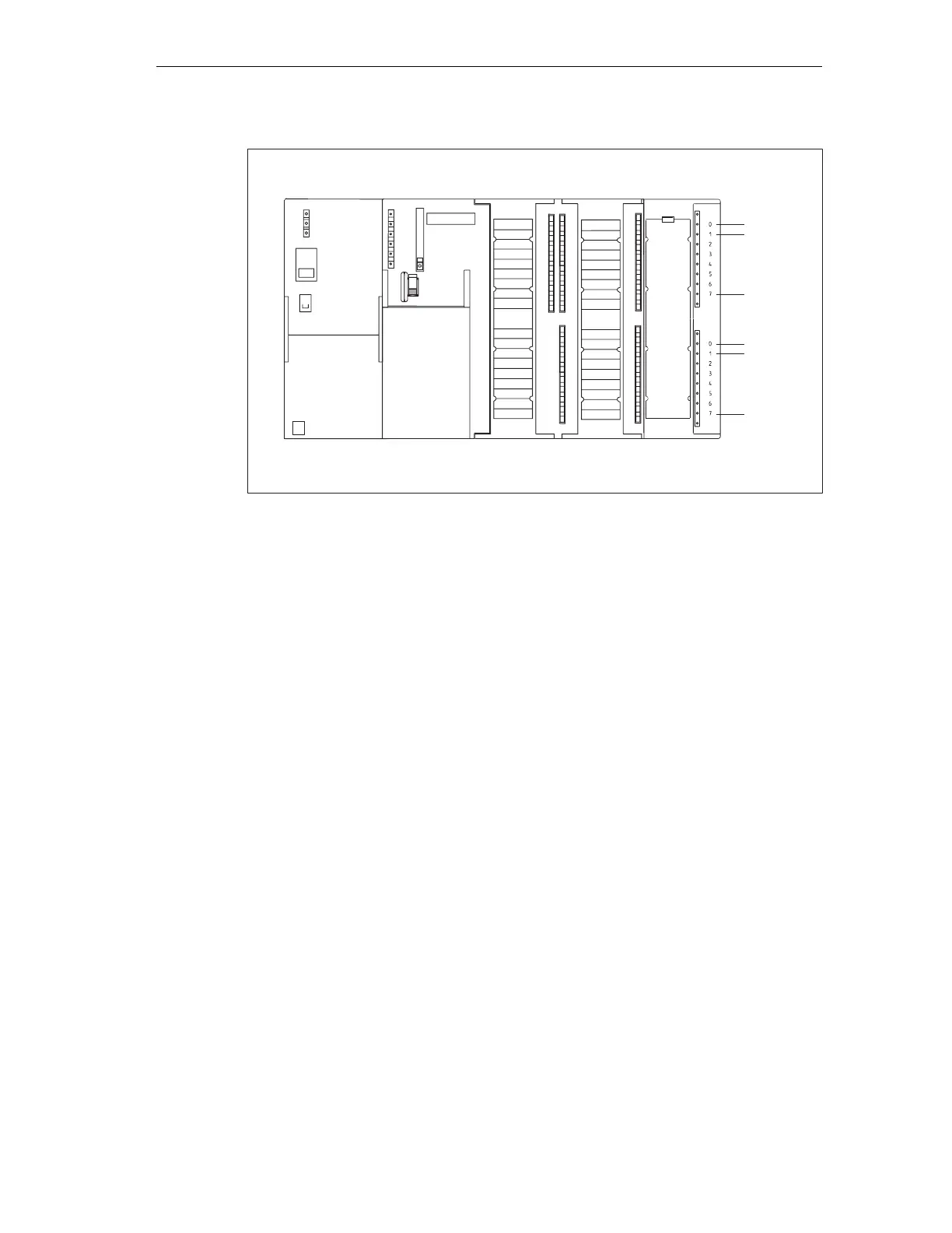
Slot
number
Address 0.0
Address 1.1
Address 0.1
Address 0.7
Address 1.7
Address 1.0
4
SM (digital modules)
:
:
:
:
:
:
1
PS
CPU
2
SF
BUSF
DC5V
FRCE
RUN
STOP
SIEMENS
Figure 7-3 I/O Addresses of a digital module in Slot 4
Addresses of the analog modules
The address of an analog input or output channel is always a word address.
The channel address depends on the module start address.
If the first digital module is inserted in slot 4 its default start address is 256. The
start address of any further analog modules is incremented by 16 per slot (see the
Figure in Chapter Slot-based Addressing of Modules).
An analog I/O module has the same start addresses for its input and output
channels.
An example for analog modules
The example in the figure below shows you which default channel addresses are
obtained if an analog module is inserted in slot 4. As you can see, the input and
output channels of an analog I/O module are addressed starting at the same
address, namely the module start address.
Slot number 3 has not been assigned since there is no interface module in the
example.
 Loading...


