Configuring
S7-300 Programmable Controller Hardware and Installation
A5E00105492-01
4-25
All CPUs except CPU 31xC
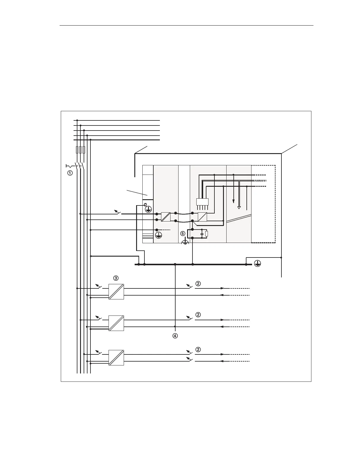
The figure below shows you the complete assembly of an S7-300 with TN-S mains
supply (does not apply to CPU 31xC).
Apart from powering the CPU, the PS 307 also supplies the load current for the 24
VDC modules.
Note: The arrangement displayed does not correspond with the physical
arrangement; it was merely selected to give you a clear overview.
low-voltage distribution
e. g. TN-S System (3 x 400 V)
cabinet
Rail
Ground bus in cabinet
PS
CPU
SM
Signal modules
L1
N
L+
M
µP
AC 24 to 230V load circuit for AC modules
DC 5 to 60V load circuit for non-isolated
DC modules
DC 5 to 60V isolated for
DC modules
AC
AC
AC
AC
DC
DC
L1
M
L2
L3
N
PE
Figure 4-12 Grounding conception S7-300 ( not with CPU 31xC)
 Loading...


