Appendix
S7-300 Programmable Controller Hardware and Installation
11-14 A5E00105492-01
• The lower the impedance of an equipotential conductor, the more effective is
equipotential bonding.
• When shielded signal cables interconnect two system components and the
shielding is connected on both ends to ground/protective conductors, the
impedance of the additionally installed equipotential conductor must not exceed
10% of the shielding impedance.
• The cross-sectional dimension of an equipotential conductor must be sufficient
to handle the maximum equipotential current flow. Practical and proven
equipotential conductor cross-section is 16 mm
2
.
• Always use equipotential conductors made of copper or galvanized steel.
Always connect the cables on a large surface to the equipotential
busbar/protective conductor and protect it against corrosion.
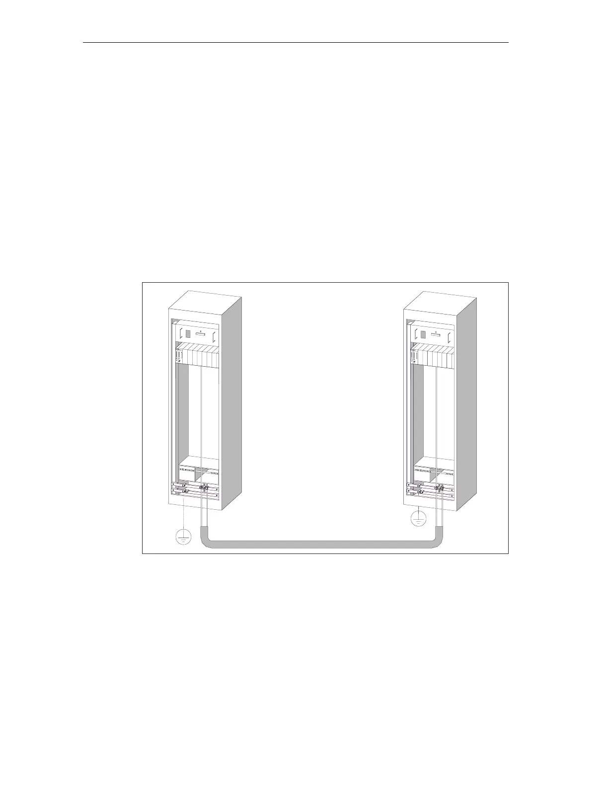
• Route your equipotential conductor to minimize the area between the
equipotential conductor and signal lines as far as possible (see the figure
below).
Figure 11-5 Equipotential bonding
11.2.7 Cable routing inside buildings
Introduction
Inside buildings (inside and outside cabinets), clearances must be maintained
between groups of different cables to achieve the necessary electromagnetic
 Loading...


