Commissioning
S7-300 Programmable Controller Hardware and Installation
8-32 A5E00105492-01
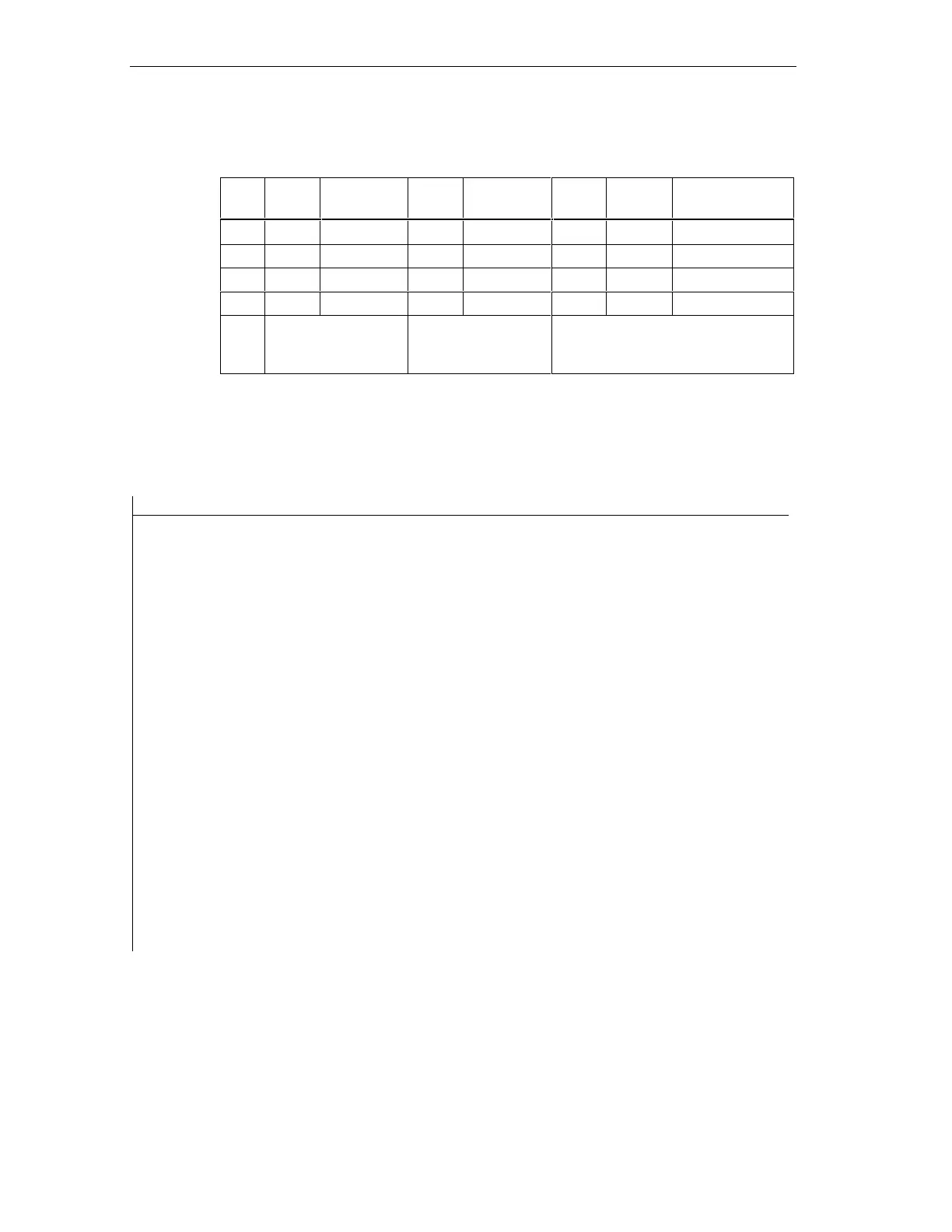
Table 8-10 Configuration example for the address areas in intermediate memory
Type Master
address
Type Slave
address
Lengt
h
Unit Consistency
1 E 222 A 310 2 Byte Unit
2 A 0 E 13 10 Word Total length
:
32
Address areas in the
DP master CPU
Address areas in the
DP slave CPU
These address area parameters
must be identical for DP master and
DP slave
Sample program
Below you will see a small sample program for data exchange between DP master
and DP slave. The addresses used in the example are found in the table above.
In the DP Slave CPU In the DP Master CPU
L 2 Data pre-
T MB 6 processing in
the
L IB 0 DP Slave
TMB7
L MW 6 Passing data
T PQW 310 to the
DP master
L PIB 222 // processing
data received
T MB 50 in the DP Master
L PIB 223
L B#16#3
+I
TMB 51
L 10 //Data pre-
processing in the
+ 3 DP master
TMB 60
CALL SFC 15 //send Data
LADDR:= W#16#0 to DP slave
RECORD:= P#M60.0 Byte
20
RET_VAL:=MW 22
 Loading...


