Wiring
S7-300 Programmable Controller Hardware and Installation
A5E00105492-01
6-11
6.6 Inserting front connectors into modules
Prerequisite
The front connectors are completely wired as described in the Chapter Wiring front
connectors .
Inserting the front connector
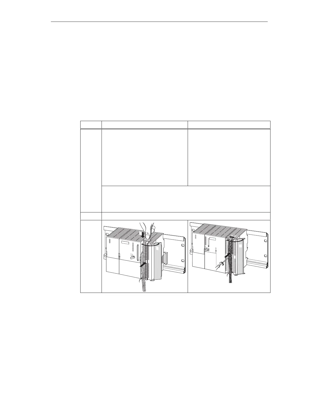
Table 6-7 Inserting the front connector
Step with 20-pin front connector with 40-pin front connector
Push in the unlocking mechanism on top
of the module (1).
Hold the unlocking mechanism in this
position and insert the front connector
into the module (1a).
Provided the front connector is seated
correctly in the module, the unlocking
mechanism automatically returns to
initial position when you release it.
Screw-tighten the fixing screw in the
center of the connector (1).
This pulls the front connector
completely into contact with the
module.
1.
Note
When you insert the front connector into the module, an encoding mechanism
engages in the front connector, thus ensuring that the connector can only be
inserted in modules of the same type.
2. Close the front panel (2).
–
1a
1
2
1
2
 Loading...


