Configuring
S7-300 Programmable Controller Hardware and Installation
A5E00105492-01
4-35
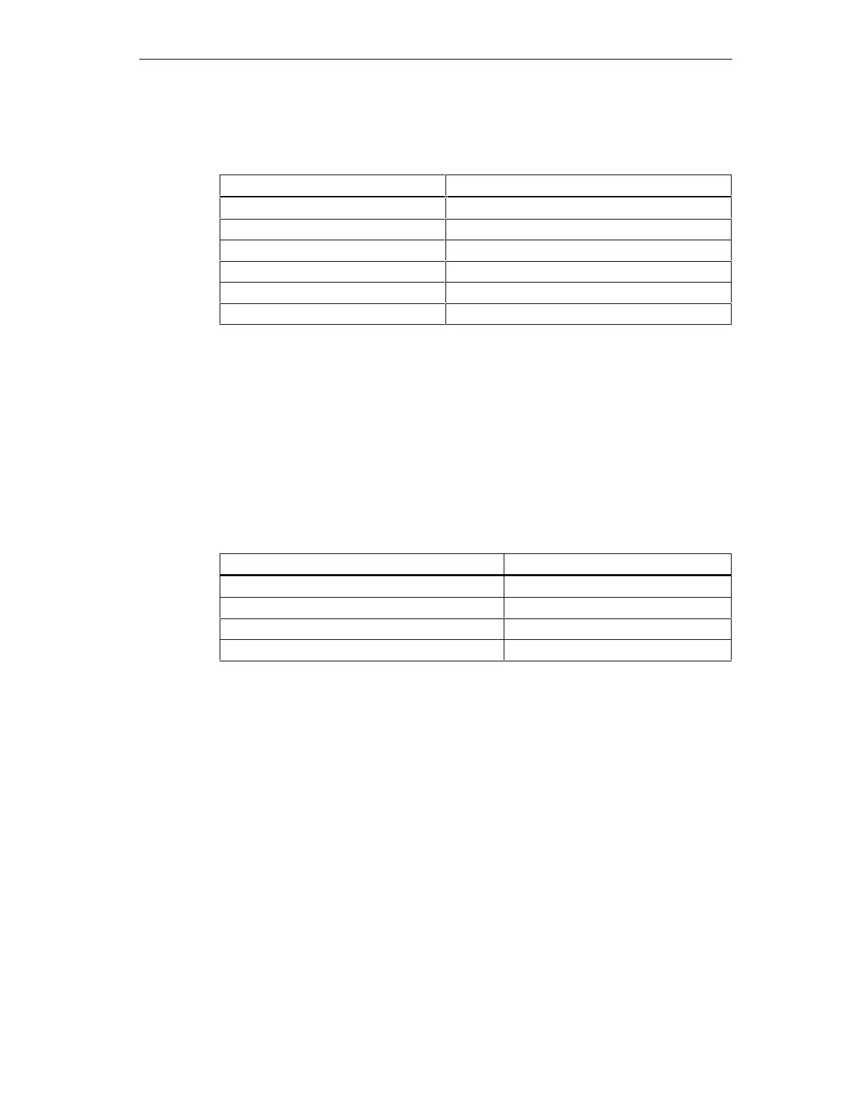
The table below lists the properties of these bus cables.
Table 4-16 Properties of PROFIBUS cables
Properties Values
Impedance level approx. 135 Ω to 160 Ω (f = 3 MHz to 20 MHz)
Loop resistance ≤ 115 Ω/km
Effective capacitance 30 nF/km
Attenuation 0.9 dB/100 m (f = 200 kHz)
Permissible conductor cross-sections 0.3 mm
2
to 0.5 mm
2
Permissible cable diameter 8 mm ± 0.5 mm
Wiring bus cables
When wiring PROFIBUS cables, you must not
• twist,
• stretch
• or compress them.
When wiring indoor bus cables, also maintain the following marginal conditions
(d
A
= outer cable diameter):
Table 4-17 Marginal conditions for wiring interior bus cables
Characteristics Condition
Bending radius (one-off) ≥ 80 mm (10 x d
A
)
Bending radius (multiple times) ≥ 160 mm (20 x d
A
)
Permissible temperature range during installation –5 °C to +50 °C
Shelf and stationary operating temperature range –30 °C to +65 °C
Cross-reference
If you want to use optical waveguide cables for PROFIBUS, you can find further
information on this topic in the Manual SIMATIC NET, PROFIBUS Networks.
 Loading...


